
Method for forming organic light-emitting layer

a technology of organic light and layer, applied in the direction of coating, solid-state device, chemical vapor deposition coating, etc., can solve the problems of non-uniform mq/sub>layer and cannot be produced on a commercial scal

Inactive Publication Date: 2007-08-16
MECAROENERGY CO LTD
View PDF12 Cites 6 Cited by
  • Summary
  • Abstract
  • Description
  • Claims
  • Application Information

AI Technical Summary

Benefits of technology

[0011] Further, the inner reaction temperature of the reaction chamber is preferably controlled to 15˜500° C. in order to increase the reaction rate and improve the characteristics of the layer.
[0017] If necessary, the method of the present invention may further comprise the step of removing unreacted raw materials and by-products by purging after step 2) and prior to step 3) or after step 3). The optional step is preferred in terms of shortened overall process time and improved characteristics of the final layer.
[0019] Further, the inner reaction temperature of the reaction chamber is preferably controlled to 15˜500° C. in order to increase the reaction rate and improve the characteristics of the thin layer.
[0021] In the chemical vapor deposition or molecular layer deposition employed in the method of the present invention, a purge gas selected from the group consisting of helium (He), hydrogen (H2), nitrogen (N2) and argon (Ar) is supplied to the reaction chamber, and gases present in the reaction chamber are removed by suction using a vacuum pump disposed in the reaction chamber, thereby shortening the purging time and thus shortening overall process time.

Problems solved by technology

Although thermal evaporation has the advantage of easy formation of an Mqn layer, it has the problems that the Mqn layer is non-uniform and cannot be produced on a commercial scale.

Method used


Image

  • Method for forming organic light-emitting layer
  • Method for forming organic light-emitting layer
  • Method for forming organic light-emitting layer

Examples


example 1

[0036] In this example, a method for forming a light-emitting layer by chemical vapor deposition is described.

[0037] A substrate 22 (ITO coated glass, film or wafer) is mounted on a heating susceptor 20 arranged inside a reaction chamber 10. Thereafter, the inner temperature of the reaction chamber 10 is maintained at a temperature suitable for reaction. The reaction temperature range is preferably room temperature to 500° C. As used herein, the term “room temperature” is defined as an ambient temperature between about 15° C. and about 25° C.

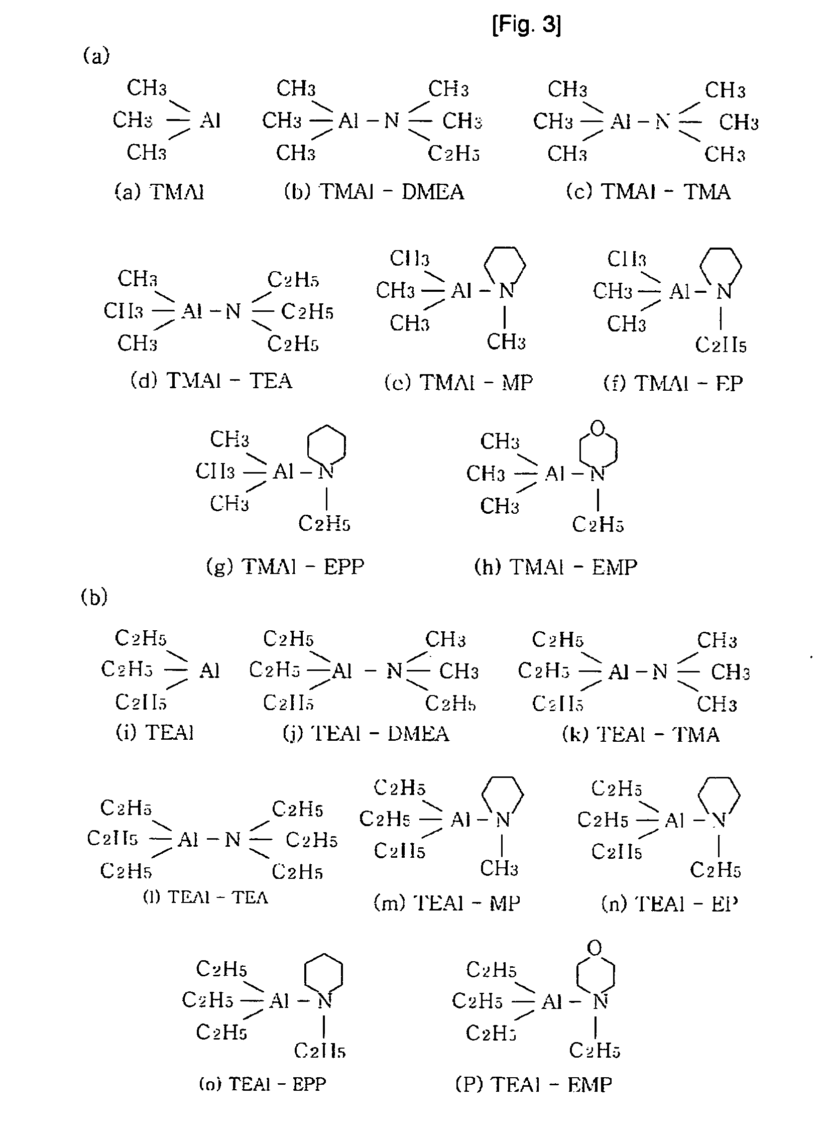
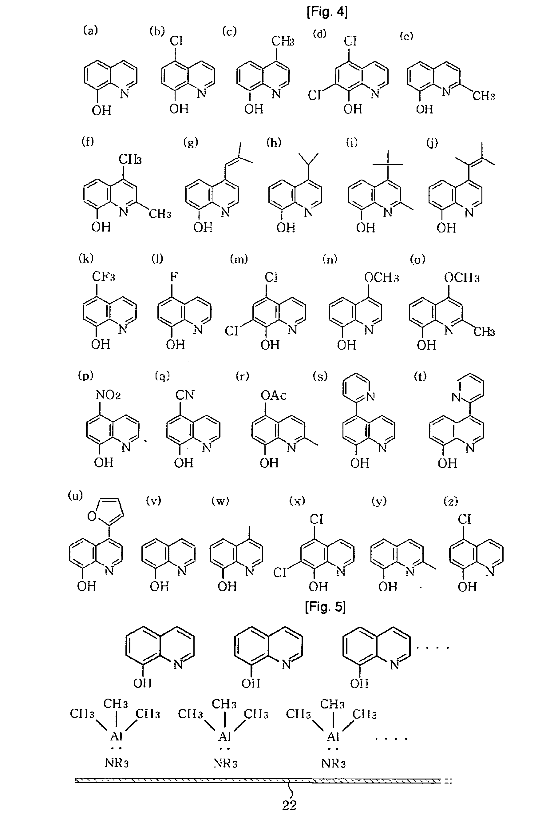
[0038] After the inner reaction temperature of the reaction chamber 10 is stabilized, a metal-containing material and an 8-hydroxyquinoline derivative are fed into the reaction chamber 10. The metal-containing material is selected from aluminum-, gallium- and zinc-containing materials. The aluminum-containing material is selected from the sixteen compounds shown in FIG. 3 and the compounds listed in Table 1 below. The aluminum-containing mater...

example 2

[0053] In this example, a method for forming an Alq3 layer by molecular layer deposition is described.

[0054] A substrate 22 is mounted on a susceptor 20 arranged inside a reaction chamber 10. Thereafter, the inner temperature of the reaction chamber 10 is maintained at a temperature suitable for reaction. The reaction temperature range is preferably room temperature to 500° C. As used herein, the term “room temperature” is defined as an ambient temperature between about 15° C. and about 25° C.

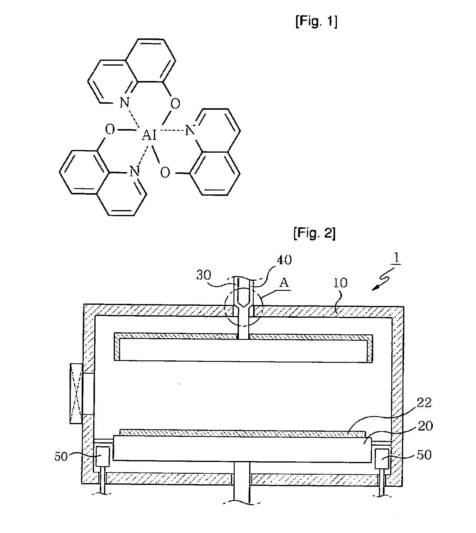
[0055] After the inner reaction temperature of the reaction chamber 10 is stabilized, an aluminum-containing material is fed into the reaction chamber 10. The aluminum-containing material is selected from the sixteen compounds having the structures shown in FIG. 3 and some compounds are listed in Table 1. The aluminum-containing material is vaporized before being fed into the reaction chamber 10. Since the aluminum-containing material has good vaporization characteristics, they can be easily ...


PUM

PropertyMeasurementUnit
reaction temperatureaaaaaaaaaa

Abstract

Disclosed herein is a method for forming a light-emitting layer on an industrial scale via chemical vapor deposition or molecular layer deposition. According to the method, a metal-containing material and an 8-hydroxyquinoline derivative having stable vapor pressure characteristics are used as raw materials and are vaporized.

Description

TECHNICAL FIELD [0001] The present invention relates to a method for forming an organic light-emitting layer, and more particularly to a method for forming an organic light-emitting layer on an industrial scale via chemical vapor deposition (CVD) or molecular layer deposition (MLD). BACKGROUND ART [0002] Organic light-emitting layers are commonly made of Mqn wherein M is a metal selected from aluminum, gallium and zinc, q is 8-hydroxyquinoline derivatives, and n is an integer of 1 to 3. [0003] Among these, Alq3 is a compound having the structure shown in FIG. 1, and is a representative material for a light-emitting layer of an organic electroluminescent (EL) device. Conventional methods for forming a Mqn layer on a substrate employ thermal evaporation, which is a physical vapor deposition (PVD) process. [0004] Thermal evaporation is a process wherein Mqn molecules are fed into a reaction furnace and then deposited on a substrate by heating to a high temperature. Although thermal eva...

Claims


Application Information

Patent Timeline
Patent Type & Authority Applications(United States)
IPC IPC(8): C23C16/00H01L21/205
CPCH01L51/0002H01L51/0079H01L51/0003H10K71/10H10K71/12H10K85/321
Inventor JANG, HYUK-KYOOKIM, HYUN-CHANG
Owner MECAROENERGY CO LTD
Learn More