[0026] According to the first form of the present invention, by bringing the projection end of cathode surface having flatness or minute unevenness shape into contact with the anode surface having flat surface, the arc plasma generation can be induced through flowing of
electric current into said contact point. When said projection end evaporated by emission of arc plasma, at the time of next plasma start, another projection end which can be brought into contact with said anode surface becomes a new plasma emission point, and the plasma can be generated persistently. The tip of conventional trigger-and-anode is formed in the shape of a stick. Accordingly, when the plasma is generated by making the trigger-and-anode come in contact with said cathode surface, the emission bore having the size of tip
diameter of said trigger-and-anode is formed on said cathode surface. In a
vacuum arc discharge, the
cathode material with which the emission bore was filled is emitted as plasma or droplets. In addition, since cathode point has a property to move without staying in a constant point, the cathode surface is damaged slowly with increasing of the number of times even if it is an
electric discharge of a short time for around several seconds. In general, circumference of the place where the trigger
electrode contacts with is eroded. Therefore, in the plasma generator performing persistently the intermittent repetition such as start, sustaining and stop for a long time, it was necessary that the abrasion member
grinding the cathode surface is disposed and the cathode surface is ground regularly. However, a large quantity of mine dust occurs by the
grinding process and then
pollution in
vacuum chamber was caused. In addition, said
pollution was one of causes falling the operation efficiency of the plasma generator.
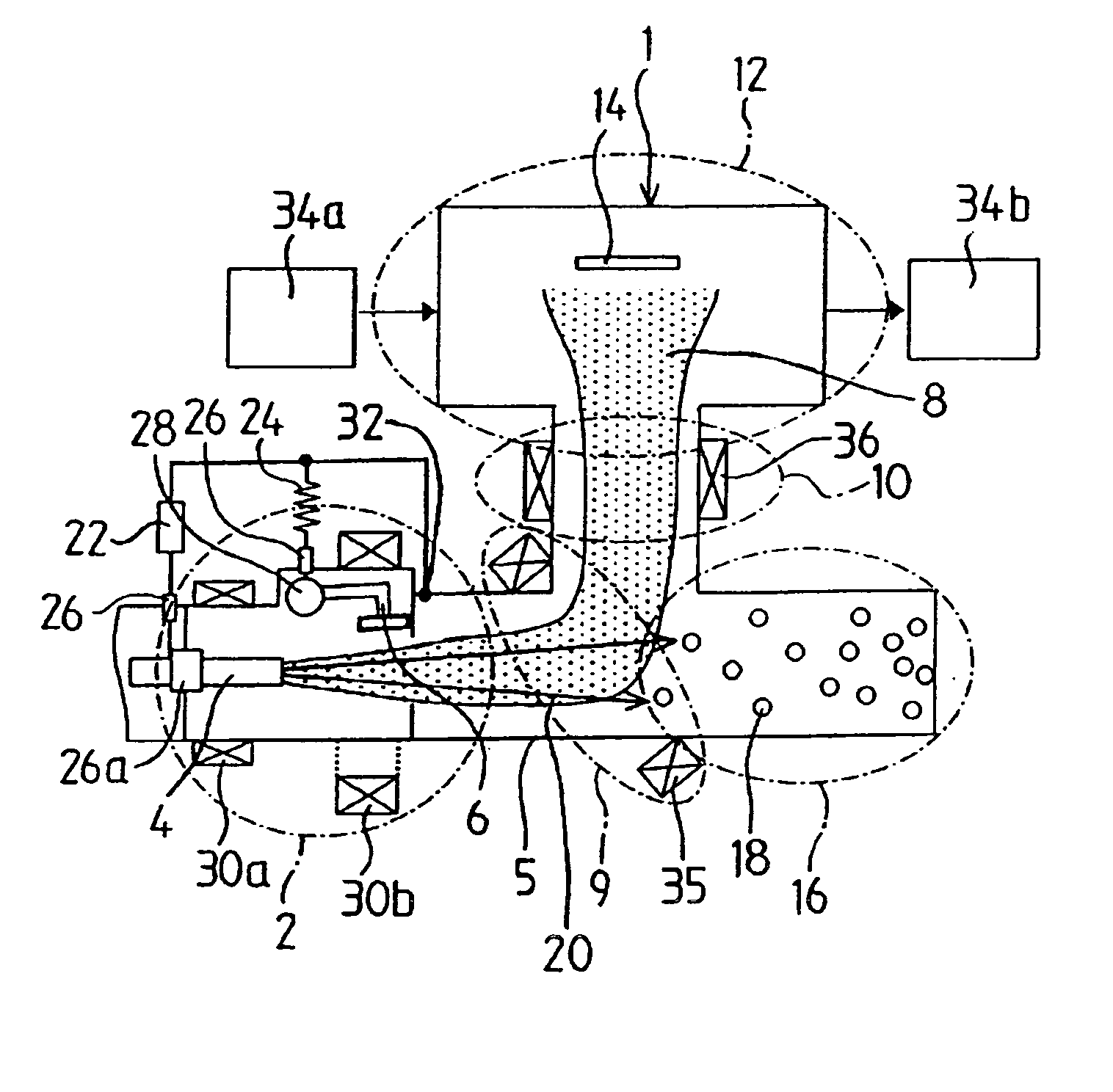
[0027] In the plasma generator of the present invention, the plasma occurs from the plasma emission point that the projection end formed on cathode surface contacts with anode surface, and when this projection end evaporated, at next
start time of plasma, another projection end capable of contacting with said anode surface becomes new plasma emission point. Even when some projection ends evaporate sequentially, the minute unevenness shape of cathode surface is held because the projection ends are formed in sequence, so that the plasma can be generated persistently from said cathode surface and the generation of plasma is realized stably and intermittently without opening of the vacuum chamber. Besides, since the cathode surface is consumed uniformly during long time, the cathode surface gradually retreats, so that the
vacuum arc discharge continues till the
cathode material disappears and the continuous generation of plasma is enabled until perfect disappearance of cathode.
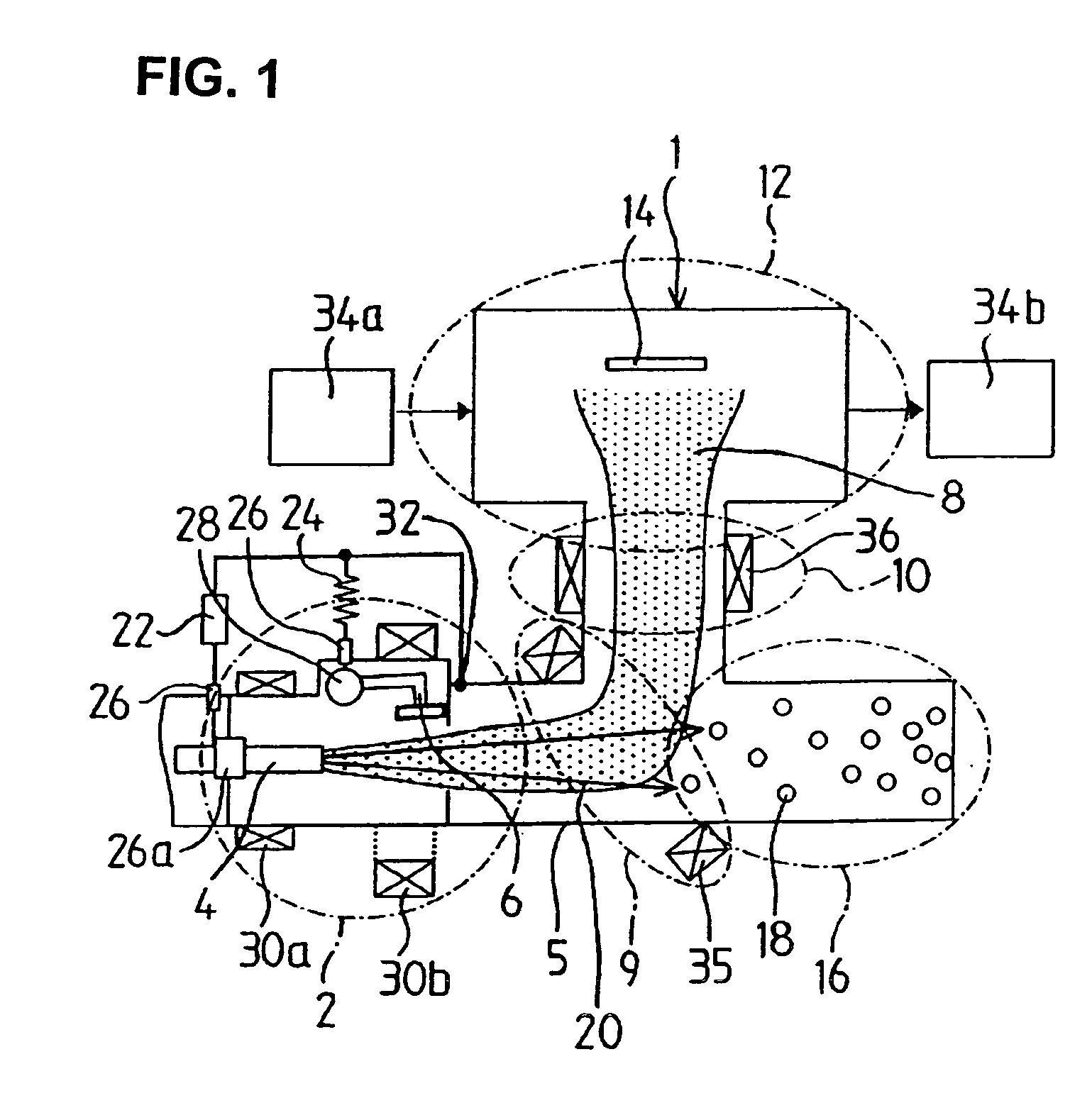
[0028] According to the second form of the present invention, the driving mechanism is provided with the trigger-and-anode and by this driving mechanism, the trigger-and-anode can move for repetition between the plasma starting position and the plasma collision avoiding position. When said trigger-and-anode is separated from cathode surface, a cathode point is formed on the cathode surface, and the vacuum arc plasma is formed diffusely from said cathode point toward the trigger-and-anode direction through an
electric field. Furthermore, most of vacuum arc plasma occurred diffusely can be sent to drawing side by moving the trigger-and-anode to the plasma collision avoiding position. In addition, since one part of plasma constituent particles arrive at the trigger-and-anode, the
electric discharge can be maintained.
[0029] According to the third form of the present invention, since the driving mechanism is connected to the base end portion of said trigger-and-anode so that said trigger-and-anode can swing for repetition between the plasma starting position and the plasma collision avoiding position as a fulcrum in said driving mechanism, the stable swing motion of said trigger-and-anode can be realized. Swing of the trigger-and-anode as a fulcrum in the driving mechanism draws an arc-shaped
orbit, and the trigger-and-anode can move from the plasma starting position to the plasma collision avoiding position smoothly, while sweeping the plasma by the
voltage applied between cathode and trigger-and-anode.
[0030] According to the fourth form of the present invention, since said trigger-and-anode is formed in the hammer shape having an anode base end portion of a narrow width and an anode tip end portion of wide width, said cathode surface can completely abut with the entire surface of anode surface at the time of plasma start, and a good contact state between the anode surface and projection end can be assured. In addition, since the position of center of gravity of trigger-and-anode is located at the anode tip end portion side, said swing motion of this trigger-and-anode can be composed from a single
pendulum-like stable repetition motion.
[0031] According to the fifth form of the present invention, since the permanent
magnet or the
electromagnet is arranged at tip end portion of said trigger-and-anode, a plasma
stream to maintain the arc discharge can be concentrated to the central portion of said trigger-and-anode and it can be prevented that a membrane bonds to circumference of said trigger-and-anode. When an electro-
conductive membrane bonds to an insulator of anode circumference, its part also acts as an anode and as a result, the use efficiency of
evaporation material decreases because the
evaporation material occurred from the cathode point is transported toward said part. In addition, said trigger-and-anode can be used as an active anode. That is to say, when the permanent
magnet or the
electromagnet is arranged at the tip end portion of said trigger-and-anode so that an arc
electric current is concentrated to the central portion of said trigger-and-anode, the plasma spreading in front of the anode surface of said trigger-and anode is converged and accordingly activation and high
ionization can be achieved.
Magnet can be disposed in the inside of trigger-and-anode or the outside. Especially, when the
magnet is buried in the inside of anode, the effectiveness of magnet increases because the magnet surface does not touch with cathode.
Plasma is concentrated to the vicinity of anode surface by
electromagnetic interaction (Lorenz force) between the
magnetic field of the permanent magnet or
electromagnet and the plasma, so that a plasma high-density domain (plasma plume) can be formed. When neutral atoms emitted from the cathode is incident to the plasma plume, the neutral atoms are formed to plasma components by
ionization, so that the plasma can be generated with high efficiency because said trigger-and-anode composes an active anode. Namely, one part of the neutral particles occurring from the cathode can be ionized by making said trigger-and-anode active. In other words, since one part of the neutral particles not contributing for layering can be utilized, it can make the speed of layering increase.

