
Method of manufacturing charged particle, charged particle, electrophoretic dispersion liquid, electrophoretic sheet, electrophoretic device and electronic equipment

a technology charge particle, which is applied in the direction of optics, instruments, optical elements, etc., can solve the problems of large power consumption of electrophoretic display device, insufficient electric field sensitiveness, and difficulty in obtaining electrophoretic particles with sufficient electric charg

Active Publication Date: 2007-08-23
E INK CORPORATION
View PDF14 Cites 10 Cited by
  • Summary
  • Abstract
  • Description
  • Claims
  • Application Information

AI Technical Summary

Benefits of technology

[0009]An advantage of the present invention is to provide a method of manufacturing a charged particle with which the amount of electric charge of the particle can be controlled, and a charged particle whose sensitivity to an electric field is controllable. Another advantage of the present invention is to provide electrophoretic dispersion liquid, an electrophoretic display sheet, an electrophoretic device and electronic equipment that are reliable since they use such charged particles.
[0010]A method of manufacturing a charged particle according to the first aspect of the invention, includes: a) providing a mother particle; and b) forming a coating layer that covers at least a part of a surface of the mother particle. The step b) includes: coupling a first chemical compound having at least a part where is going to be a starting point of living polymerization to the surface of the mother particle; and polymerizing a second chemical compound having an ionic group or a functional group convertible to an ionic group so as to form a polymer through the living polymerization that starts from the starting point of the first chemical compound.
[0011]According to the first aspect of the invention, it is possible to control the amount of the electric charge of the particle.
[0012]A method of manufacturing a charged particle according to the second aspect of the invention, includes: a) providing a mother particle; and b) forming a coating layer that covers at least a part of a surface of the mother particle. The step b) includes: coupling a first chemical compound having at least a part where is going to be a starting point of living polymerization to the surface of the mother particle; polymerizing a second chemical compound so as to form a polymer through the living polymerization that starts from the starting point of the first chemical compound; and converting at least a part of the polymer to an ionic group.
[0013]According to the second aspect of the invention, it is possible to control the amount of the electric charge of the particle.
[0014]A method of manufacturing a charged particle according to a third aspect of the invention includes: a) providing a mother particle; and b) forming a coating layer that covers at least a part of a surface of the mother particle. The step b) includes: coupling a first chemical compound having at least a part where is going to be a starting point of living polymerization to the surface of the mother particle; polymerizing a second chemical compound so as to form a polymer through the living polymerization that starts from the starting point of the first chemical compound; either converting at least a part of the polymer to an ionic precursor group that is convertible to an ionic group or introducing an ionic precursor group into the polymer; and converting the ionic precursor group to an ionic group.

Problems solved by technology

However, it is difficult to obtain electrophoretic particles with sufficiently large electric charge and they are not sensitive enough to an electric field.
Accordingly, a relatively large electric field is required to move the electrophoretic particles effectively and this results in a large power consumption of the electrophoretic display device.

Method used


Image

  • Method of manufacturing charged particle, charged particle, electrophoretic dispersion liquid, electrophoretic sheet, electrophoretic device and electronic equipment
  • Method of manufacturing charged particle, charged particle, electrophoretic dispersion liquid, electrophoretic sheet, electrophoretic device and electronic equipment
  • Method of manufacturing charged particle, charged particle, electrophoretic dispersion liquid, electrophoretic sheet, electrophoretic device and electronic equipment

Examples


first embodiment

[0048]A charged particle according to a first embodiment of the invention is firstly described. The charged particle according to the first embodiment is a positively charged particle.

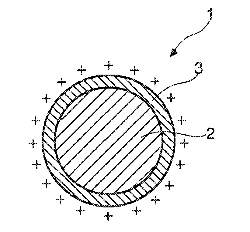
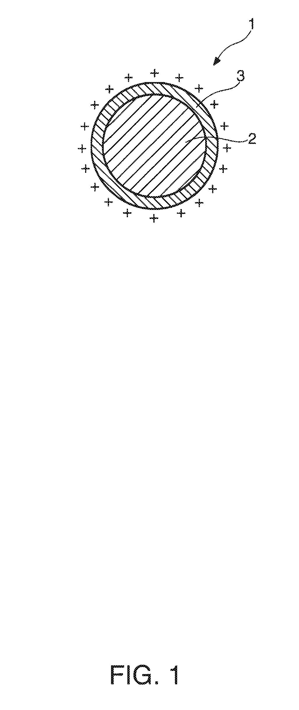
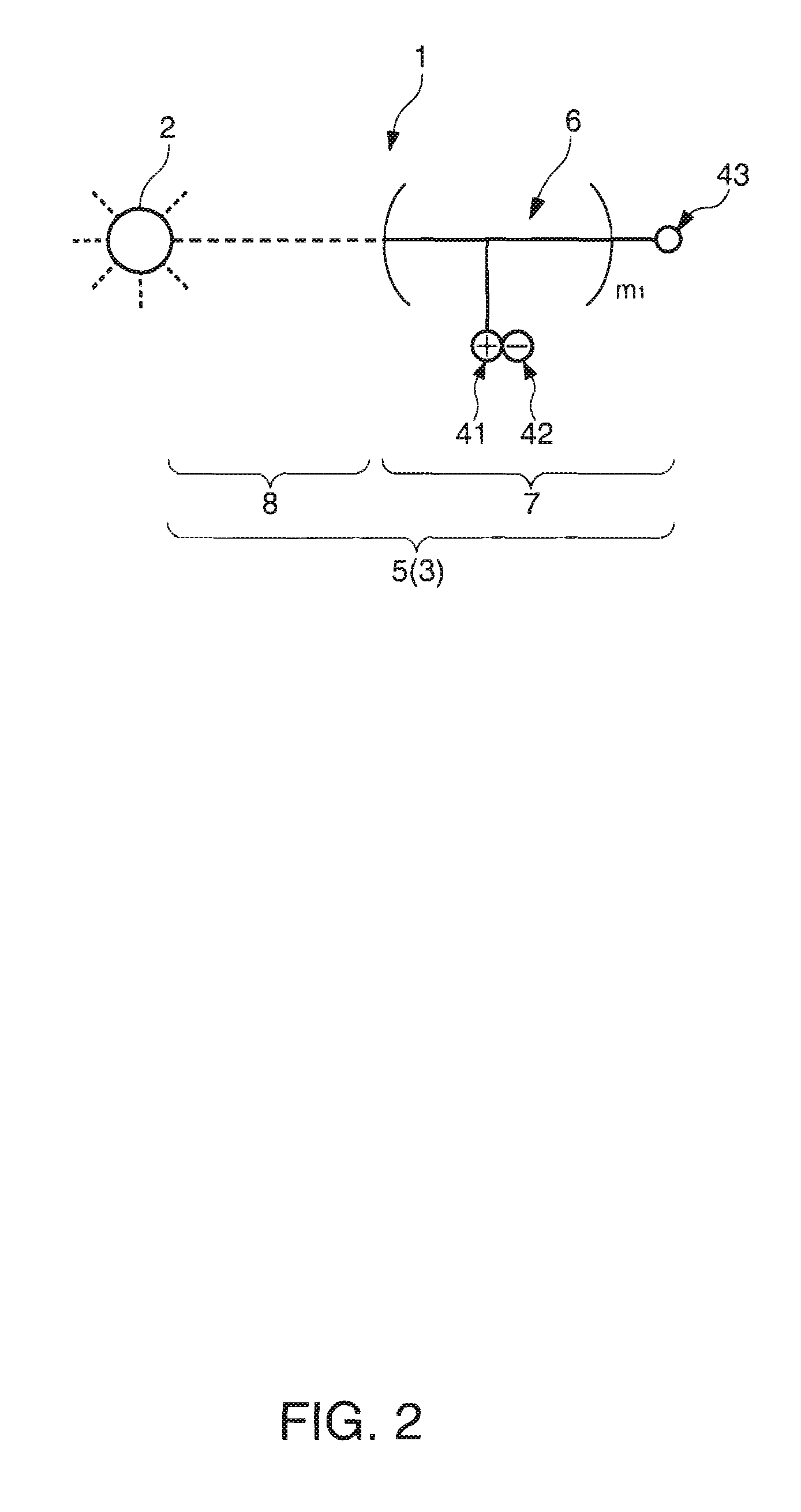
[0049]FIG. 1 is a longitudinal sectional view of a charged particle according to the first embodiment of the invention. FIG. 2 schematically shows a polymeric structure which the charged particle shown in FIG. 1 has. FIG. 3 is a schematic diagram showing an example of the polymer shown in FIG. 2.

[0050]A charged particle 1 shown in FIG. 1 includes a mother particle 2 and a coating layer 3 on the surface of the mother particle 2.

[0051]As the mother particle 2, for example, a pigment particle, a resin particle or a composite particle of pigment and resin can be used. These particles can be easily fabricated.

[0052]As specific examples of the pigment particle, there are for example aniline black, carbon black, titanium black or other black pigments; titanium dioxide, antimony trioxide, barium sulfate, zinc ...

second embodiment

[0106]A charged particle according to a second embodiment of the invention will be described. Different features and points of the charged particle 1 from that of the first embodiment will be mainly described and descriptions for the same configurations and structures will be omitted.

[0107]FIG. 5 schematically shows a polymeric structure which a charged particle according to the second embodiment has. FIG. 6 is a schematic diagram showing an example of the polymer shown in FIG. 5.

[0108]The charged particle 1 according to the second embodiment is a positively charged particle and has the same structure as that of the first embodiment except for the composition of the polymer 5 that makes up the coating layer 3. It follows that the polymer 5 of the second embodiment has the cationic group 41 at the terminal of its main chain (the other end) and at least one (more than one in this embodiment) colorant part 44 in its molecular structure.

[0109]Where the polymer 5 has the chromophore 44 (...

third embodiment

[0134]A charged particle according to a third embodiment of the invention will be described. Different features and points of the charged particle 1 from that of the first embodiment will be mainly described and descriptions for the same configurations and structures will be omitted.

[0135]FIG. 8 is a longitudinal sectional view of a charged particle according to the third embodiment. FIG. 9 schematically shows a polymeric structure which the charged particle shown in FIG. 8 has. FIG. 10 is a schematic diagram showing an example of the polymer shown in FIG. 9.

[0136]The charged particle 1 according to the third embodiment is a negatively charged particle and has the same structure as that of the first embodiment except for the composition of the coating layer 3. It follows that the coating layer 3 of the third embodiment has the polymer 5 in which the terminal (the other end) of the main chain is coupled to the surface of the mother particle 2 and an anionic group 45 (an ionic group) ...


PUM

PropertyMeasurementUnit
temperatureaaaaaaaaaa
thicknessesaaaaaaaaaa

Abstract

A method of manufacturing a charged particle, comprising: a) providing a mother particle; and b) forming a coating layer that covers at least a part of a surface of the mother particle wherein the step b) includes: coupling a first chemical compound having at least a part where is going to be a starting point of living polymerization to the surface of the mother particle; and polymerizing a second chemical compound having an ionic group or a functional group convertible to an ionic group so as to form a polymer through the living polymerization that starts from the starting point of the first chemical compound.

Description

BACKGROUND OF THE INVENTION[0001]1. Technical Field[0002]Several aspects of the present invention relate to a method of manufacturing an electrically charged particle, an electrically charged particle, electrophoretic dispersion liquid, an electrophoretic sheet, an electrophoretic device and electronic equipment.[0003]2. Related Art[0004]It has been generally known that particles move (migrate) in fluid by coulomb force when an electric filed is applied to a dispersion system in which the particles are dispersed in the fluid, and this phenomenon is called electrophoresis. An electrophoretic display device which utilizes the electrophoresis to display desired information (image) has recently attracted attention as a new display device.[0005]The electrophoretic display device has features of a display memory property where a voltage is not applied, a wide viewing angle, a high-contrast display at low power consumption, and so on.[0006]In addition, the electrophoretic display device ha...

Claims


Application Information

Patent Timeline
Patent Type & Authority Applications(United States)
IPC IPC(8): G02B26/00G02F1/167
CPCG02F2001/1678G02F1/167
Inventor MIYAZAWA, TAKASHI
Owner E INK CORPORATION
Learn More