Resonant switching power source device

a power source device and resonance technology, applied in the direction of electric variable regulation, process and machine control, instruments, etc., can solve the problems of abnormal rise of switching frequency during light load, foregoing dc-dc converter of bridge type, and reducing power conversion efficiency. , to achieve the effect of reducing section area, increasing excitation inductance (5f), and reducing excitation curren

Inactive Publication Date: 2007-08-23
SANKEN ELECTRIC CO LTD
View PDF8 Cites 15 Cited by
  • Summary
  • Abstract
  • Description
  • Claims
  • Application Information

AI Technical Summary

Benefits of technology

[0013]During no or light load (12) smaller than in usual operation, a small amount of electric current flows through resonant series circuit (14) to increase excitation inductance (5f) of transformer (5), thus reducing excitation current (ILP) for transformer (5). When load (12) becomes heavier than in usual operation while increased electric current flows through resonant series circuit (14), reduced section area (5v) in transformer (5) comes to magnetic saturation, and therefore, reduces excitation inductance (5f) to more increase excitation current (ILP) for transformer (5). Meanwhile, as second capacitor (4) in resonant series circuit (14) is electrically charged by excitation current (ILP), second capacitor (4) is charged by larger excitation current (ILP) during heavy load (12) greater than in usual operation to accumulate in second capacitor (4) sufficient amount of electric energy to be transmitted to secondary winding (2b) of transformer (5). In this way, the device can improve power conversion efficiency during no or light load while reducing power loss in transformer (5) because no large excitation current (ILP) flows for transformer (5) during light or no load. Also, the device can be stably operated in any load condition because there is neither large fluctuation nor need therefor in oscillation frequency of first and second switching elements (2, 3) between light or no and heavy load periods.

Problems solved by technology

Accordingly, power loss in transformer 5 incurred by excitation current is not lowered even during no or light load, thereby causing considerable reduction in power conversion efficiency.
However, the foregoing DC-DC converter of bridge type has a trouble in normal operation because it does not produce sufficient interwinding capacity in secondary coil under the low secondary output voltage, thereby causing switching frequency during light load to abnormally rise.
Also, it disadvantageously has a large fluctuation in switching frequency between light and heavy loads, and this prevents stabilized operation of the converter.

Method used


Image

  • Resonant switching power source device
  • Resonant switching power source device
  • Resonant switching power source device

Examples


first embodiment

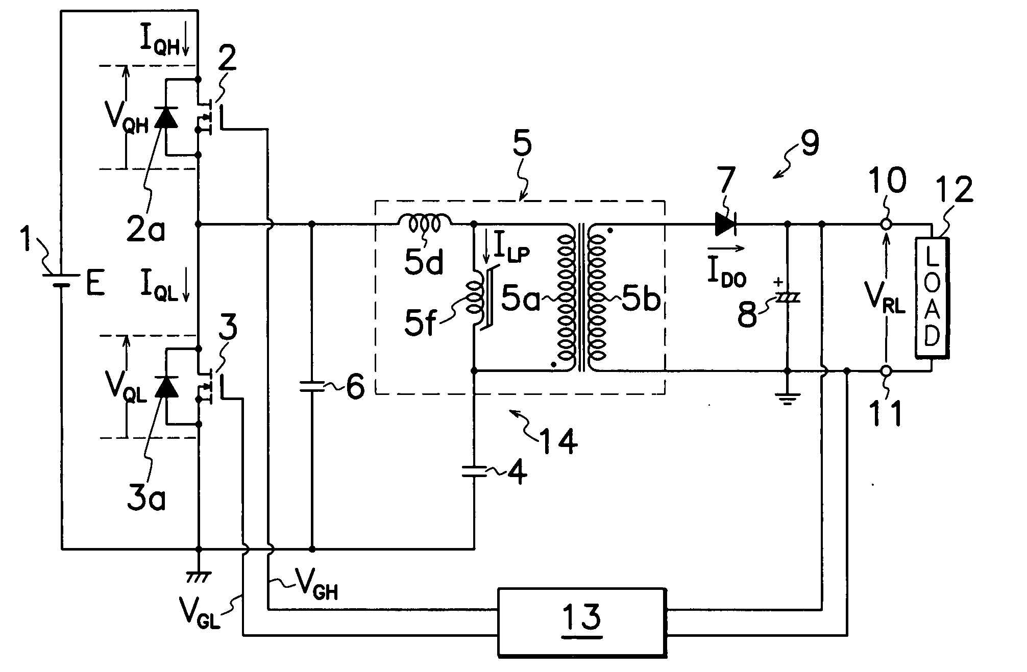
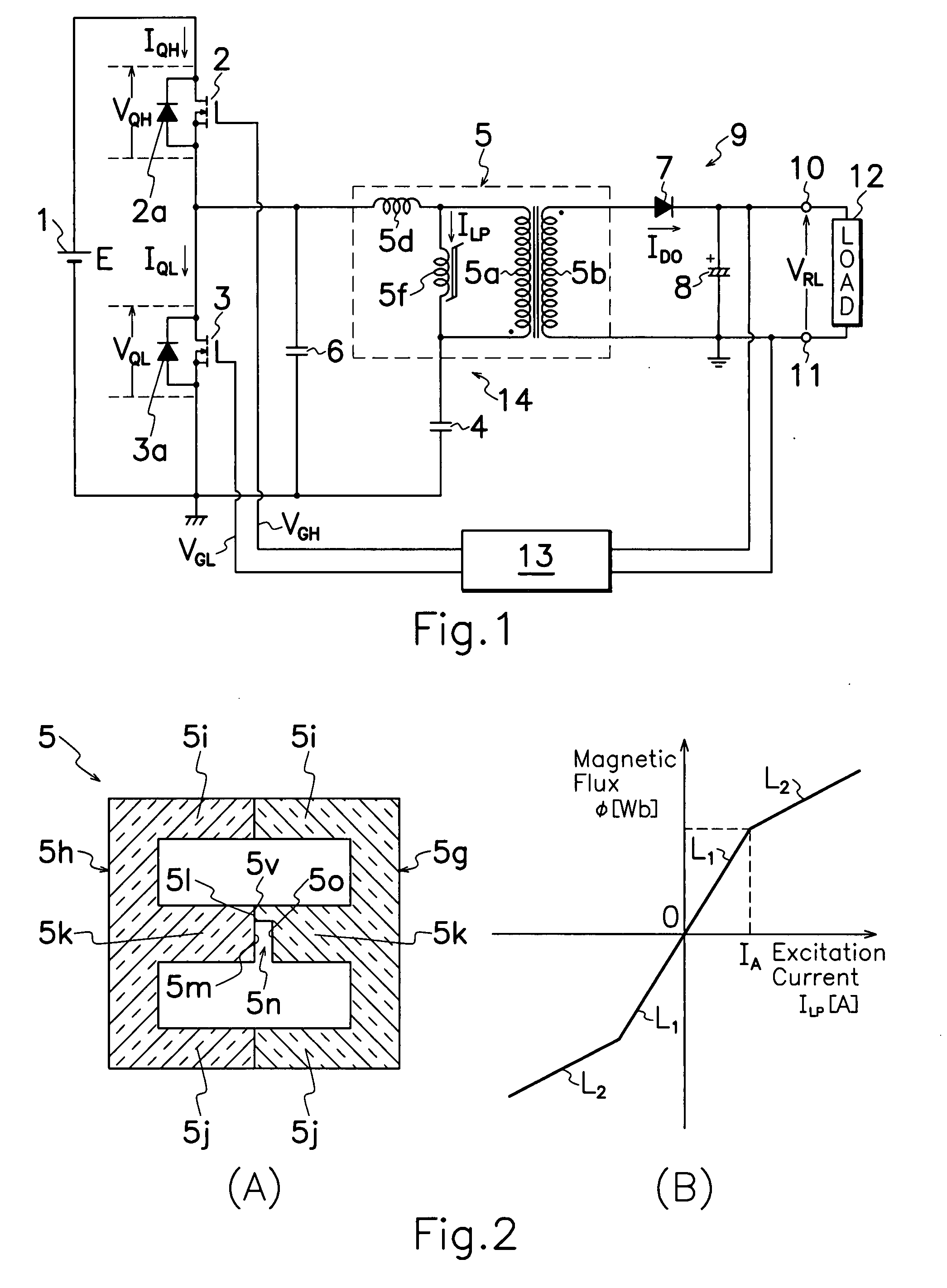
[0034]FIG. 1 is an electric circuit diagram showing the resonant switching power source device according to the present invention which has a different transformer 5 from that in the prior art device shown in FIG. 15. Specifically, the transformer 5 used in the invention's device shown in FIG. 1 comprises, as illustrated in FIG. 2 (A), a magnetic core of first and second E-shaped core halves 5g, 5h coupled together in opposed relation to each other to form a closed magnetic circuit or circuits for supporting primary and secondary windings 5a, 5b wound around first and second core halves 5g, 5h. First core half 5g has a pair of outer legs 5l and 5j and an intermediate leg 5k formed with a notch 5o on an end surface 5l of intermediate leg 5k. Second core half 5h also has a pair of outer legs 5l and 5j and an intermediate leg 5k without any notch 5o. First and second core halves 5g and 5h are positioned opposite to each other so that end surfaces 5l and 5m of facing intermediate legs 5...

fourth embodiment

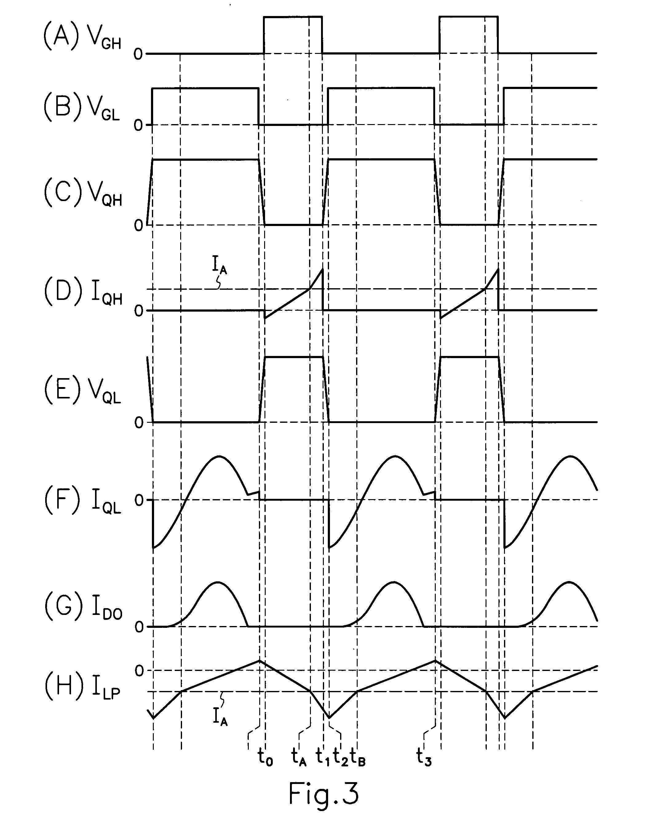
[0046]Even in fourth embodiment shown in FIG. 7, similarly to the device shown in FIG. 1, electric energy is transmitted to secondary side of transformer 5 for a half cycle in sine wave of resonance frequency determined by leakage inductance 5d and capacitance of second capacitor 4, and therefore, first and second MOS-FETs 2 and 3 are set for the on-period equivalent to or more than a half cycle in sine wave of the resonance frequency. Accordingly, a large amount of excitation current ILP flows for transformer 5 during light load, however, if a pair of E-shaped core halves 5g and 5h shown in FIG. 2 (A) are used for a core in transformer 5 shown in FIG. 7, during light load, excitation inductance 5f of transformer 5 has first inductance L1; during heavy load, when excitation current ILP for transformer 5 increases and transforms excitation inductance 5f into second inductance L2 of smaller value than that of first inductance L1; during light load a small and repressed amount of excit...

sixth embodiment

[0049]Without limitation to shapes and constructions shown in FIGS. 2 (A) and 5 (A), core halves 5g and 5h for transformer 5 shown in FIGS. 1 and 7 can be modified in various modes. For example, a sixth embodiment shown in FIG. 11 may have a tapered gap 5n defined by a pair of opposite inclined surfaces 5p and 5q on end surfaces 5l and 5m of intermediate legs 5k in a pair of E-shaped core halves 5g and 5h. Likewise, but not shown, gap 5n may be formed by providing a similar notch 5o to that in FIG. 2 (A) on end surfaces 5l and 5m of intermediate legs 5k of FIG. 11.

[0050]In addition, away from combination of paired E-shaped core halves 5g and 5h, modifications can be made as shown in FIGS. 12 and 13 to adopt E-shaped and I-shaped core halves. A seventh embodiment shown in FIG. 12 has an E-shaped core half 5g and I-shaped core half 5r positioned in opposed relation to each other to form a closed magnetic circuit or circuits, and primary and secondary windings 5a and 5b are wound aroun...


PUM


Abstract

The transformer 5 used for the present invention, comprises a core of E-shaped first and second core halves 5g, 5h coupled together in opposed relation to each other to form a closed magnetic circuit or circuits for supporting primary and secondary windings 5a, 5b wound around first and second core halves 5g, 5h; and a gap 5n defined between end surfaces 5l, 5m of first and second core halves 5g, 5h by spaced relation of end surfaces 5l, 5m to also form a reduced section area 5v by contacting the end surfaces 5l, 5m. When a large amount of electric current flows through resonant series circuit 14, reduced section area 5v comes to magnetic saturation to reduce an excitation inductance 5f of transformer 5, more increase excitation current ILP and thereby perform steady operation in any load condition. When a small amount of electric current flows through resonant series circuit 14, excitation inductance 5f of transformer 5 is increased to repress excitation current ILP, thereby reducing power loss during light or no load to improve power conversion efficiency during light load.

Description

TECHNICAL FIELD[0001]This invention relates to a resonant switching power source device, in particular, of the type capable of improving the power conversion efficiency during light or no load.BACKGROUND OF THE INVENTION[0002]Prior art current resonant switching power source devices are widely well known as beneficially indicating less noise and high power conversion efficiency because they can accomplish a zero current switching (ZCS) with a resonance circuit which converts electric current flowing through a just switched switching element into a sine wave form for reduction in switching loss. By way of an example, a prior art current resonant switching power source shown in FIG. 15, comprises a first MOS-FET 2 of high voltage side as a first switching element and a second MOS-FET 3 of low voltage side as a second switching element, first and second MOS-FETs 2 and 3 being connected in series to a DC power source 1; a first capacitor 6 for voltage resonance connected in parallel to ...

Claims


Application Information

Patent Timeline
Patent Type & Authority Applications(United States)
IPC IPC(8): H02M3/335
CPCH02M3/3376Y02B70/1491H02M2001/0058Y02B70/1433Y02B70/10H02M1/0058
Inventor SATO, MAKOTO
Owner SANKEN ELECTRIC CO LTD
Why Eureka
Try Eureka