Resonant switching power source having first and second switching elements connected in series to a DC power source
a power source and switching element technology, applied in the direction of electric variable regulation, process and machine control, instruments, etc., can solve the problems of abnormal rise of switching frequency during light load, foregoing dc-dc converter of bridge type, and reducing power conversion efficiency. , to achieve the effect of reducing section area, increasing excitation inductance (5f), and reducing excitation curren
- Summary
- Abstract
- Description
- Claims
- Application Information
AI Technical Summary
Benefits of technology
Problems solved by technology
Method used
Image
Examples
first embodiment
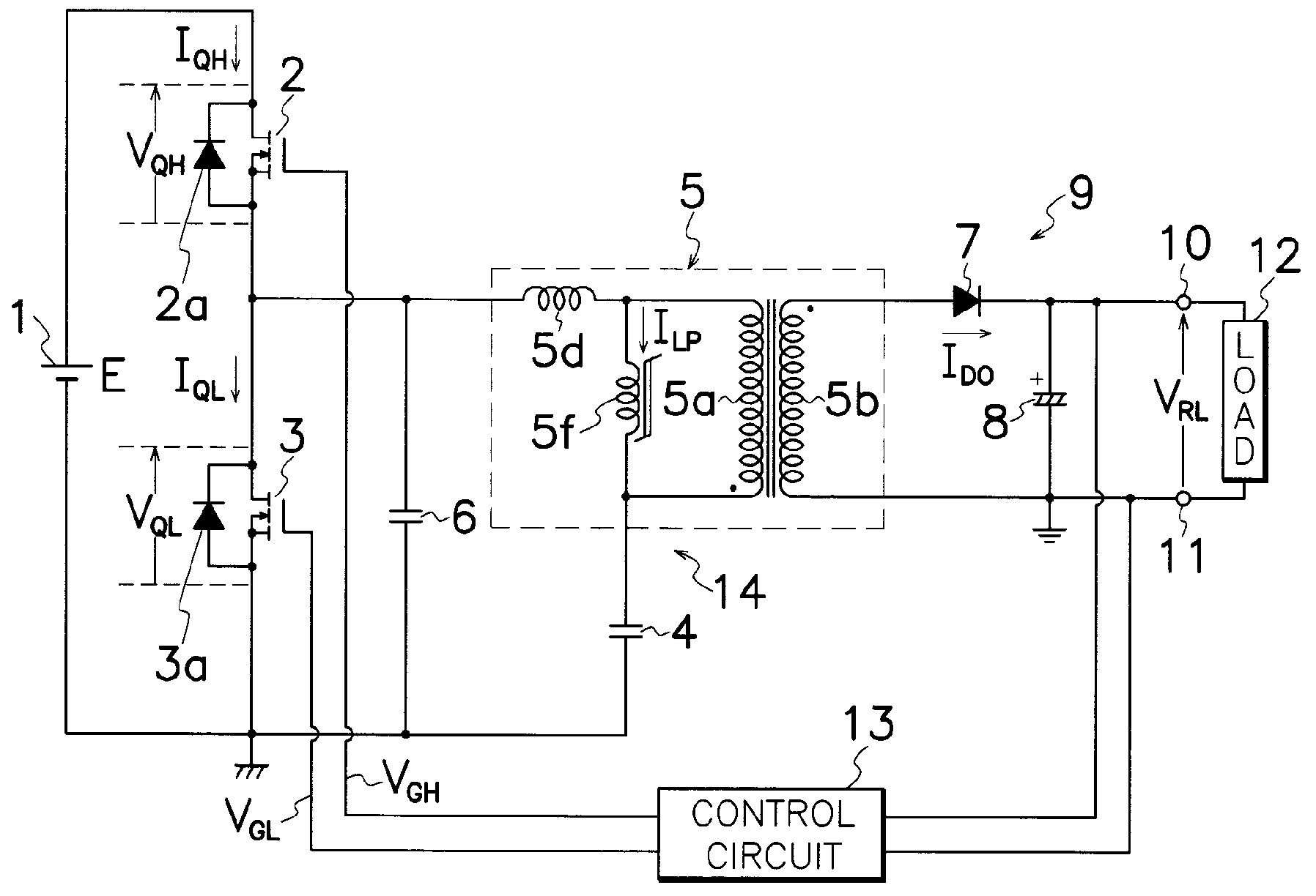
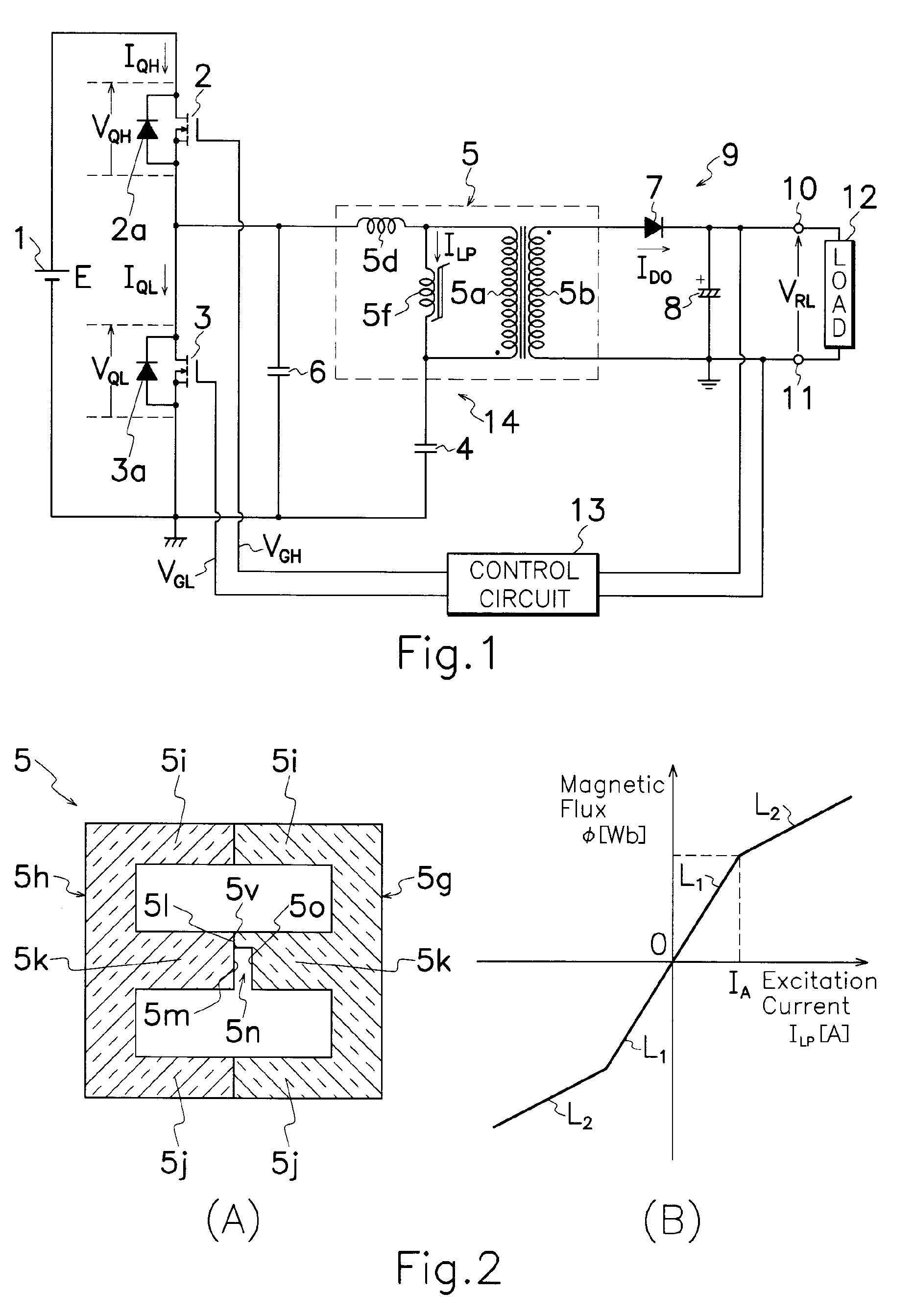
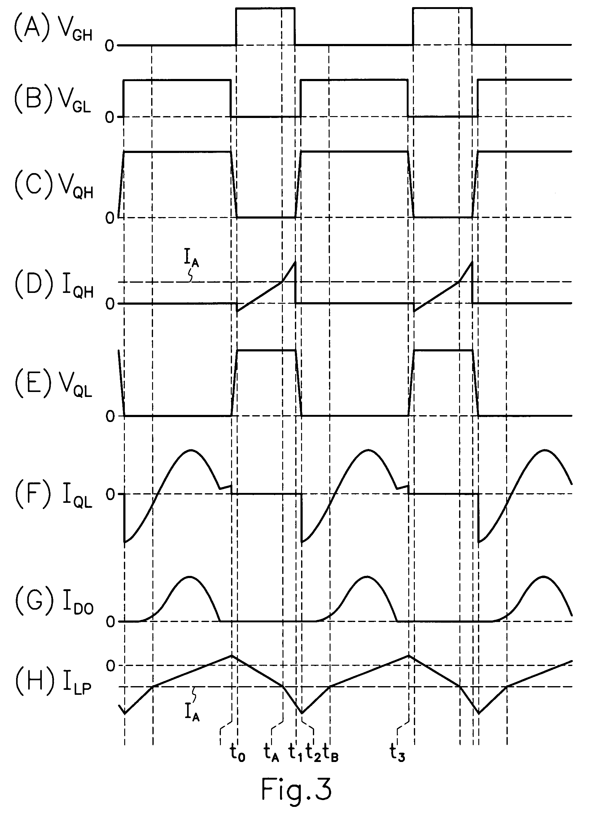
[0034]FIG. 1 is an electric circuit diagram showing the resonant switching power source device according to the present invention which has a different transformer 5 from that in the prior art device shown in FIG. 15. Specifically, the transformer 5 used in the invention's device shown in FIG. 1 comprises, as illustrated in FIG. 2 (A), a magnetic core of first and second E-shaped core halves 5g, 5h coupled together in opposed relation to each other to form a closed magnetic circuit or circuits for supporting primary and secondary windings 5a, 5b wound around first and second core halves 5g, 5h. First core half 5g has a pair of outer legs 5l and 5j and an intermediate leg 5k formed with a notch 5o on an end surface 5l of intermediate leg 5k. Second core half 5h also has a pair of outer legs 5l and 5j and an intermediate leg 5k without any notch 5o. First and second core halves 5g and 5h are positioned opposite to each other so that end surfaces 5l and 5m of facing intermediate legs 5...
fourth embodiment
[0046]Even in fourth embodiment shown in FIG. 7, similarly to the device shown in FIG. 1, electric energy is transmitted to secondary side of transformer 5 for a half cycle in sine wave of resonance frequency determined by leakage inductance 5d and capacitance of second capacitor 4, and therefore, first and second MOS-FETs 2 and 3 are set for the on-period equivalent to or more than a half cycle in sine wave of the resonance frequency. Accordingly, a large amount of excitation current ILP flows for transformer 5 during light load, however, if a pair of E-shaped core halves 5g and 5h shown in FIG. 2 (A) are used for a core in transformer 5 shown in FIG. 7, during light load, excitation inductance 5f of transformer 5 has first inductance L1; during heavy load, when excitation current ILP for transformer 5 increases and transforms excitation inductance 5f into second inductance L2 of smaller value than that of first inductance L1; during light load a small and repressed amount of excit...
sixth embodiment
[0049]Without limitation to shapes and constructions shown in FIGS. 2 (A) and 5 (A), core halves 5g and 5h for transformer 5 shown in FIGS. 1 and 7 can be modified in various modes. For example, a sixth embodiment shown in FIG. 11 may have a tapered gap 5n defined by a pair of opposite inclined surfaces 5p and 5q on end surfaces 5l and 5m of intermediate legs 5k in a pair of E-shaped core halves 5g and 5h. Likewise, but not shown, gap 5n may be formed by providing a similar notch 5o to that in FIG. 2 (A) on end surfaces 5l and 5m of intermediate legs 5k of FIG. 11.
[0050]In addition, away from combination of paired E-shaped core halves 5g and 5h, modifications can be made as shown in FIGS. 12 and 13 to adopt E-shaped and I-shaped core halves. A seventh embodiment shown in FIG. 12 has an E-shaped core half 5g and I-shaped core half 5r positioned in opposed relation to each other to form a closed magnetic circuit or circuits, and primary and secondary windings 5a and 5b are wound aroun...
PUM
 Abstract
Description
Claims
Application Information
 - R&D
- Intellectual Property
- Life Sciences
- Materials
- Tech Scout
- Unparalleled Data Quality
- Higher Quality Content
- 60% Fewer Hallucinations
Browse by: Latest US Patents, China's latest patents, Technical Efficacy Thesaurus, Application Domain, Technology Topic, Popular Technical Reports.
© 2025 PatSnap. All rights reserved.Legal|Privacy policy|Modern Slavery Act Transparency Statement|Sitemap|About US| Contact US: help@patsnap.com


