

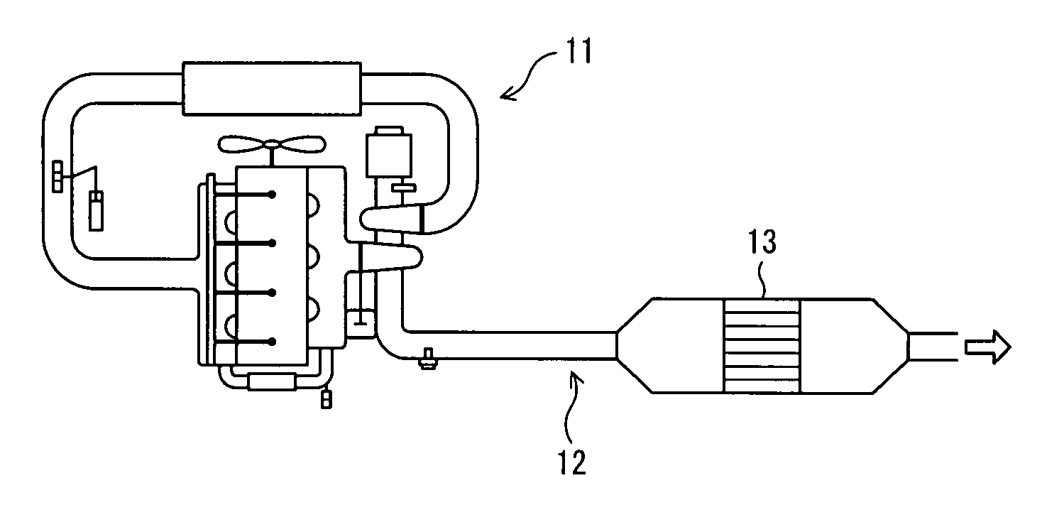
Diesel particulate filter and exhaust emission control system
a technology of particulate filter and exhaust, which is applied in the direction of machines/engines, metal/metal-oxide/metal-hydroxide catalysts, etc., can solve the problems of difficult to raise the exhaust gas temperature, lower fuel economy or dpf, and low temperature of diesel engine exhaust gas, etc., to achieve the effect of lowering the pm combustion start temperatur
- Summary
- Abstract
- Description
- Claims
- Application Information
AI Technical Summary
Benefits of technology
Problems solved by technology
Method used
Image

Examples
example
[0073] Now, showing examples, the present invention will be explained specifically but the present invention is not limited by the following embodiment but may be arbitrarily modified and put into effect without departing from the spirit of the invention.
examples 1 through 7
and Comparison Example 1 through 4
[0074] The perovskite type complex oxides were fabricated as follows.
[0075] Based on the fabrication method stipulated in Japanese Patent Application Laid-Open No. 2005-187311, particles were fabricated. For raw materials, lanthanum nitrate La(NO3)3.6H2O, barium nitrate Ba(NO3)2, iron nitrate Fe(NO3)3.9H2O, are mixed in such a manner that the mol ratio of La to Ba to Fe becomes (1−x):x:1. x was varied in the range from 0 to 1. By mixing this material salt solution with a neutralizing agent, a coprecipitate was obtained. After filtering this, the filtrate was washed with water and dried at 110° C. The powder obtained is called the precursor powder.
[0076] Then, this precursor powder is fabricated by firing after heat-treating at 800° C. for 2 hours under the atmospheric environment.
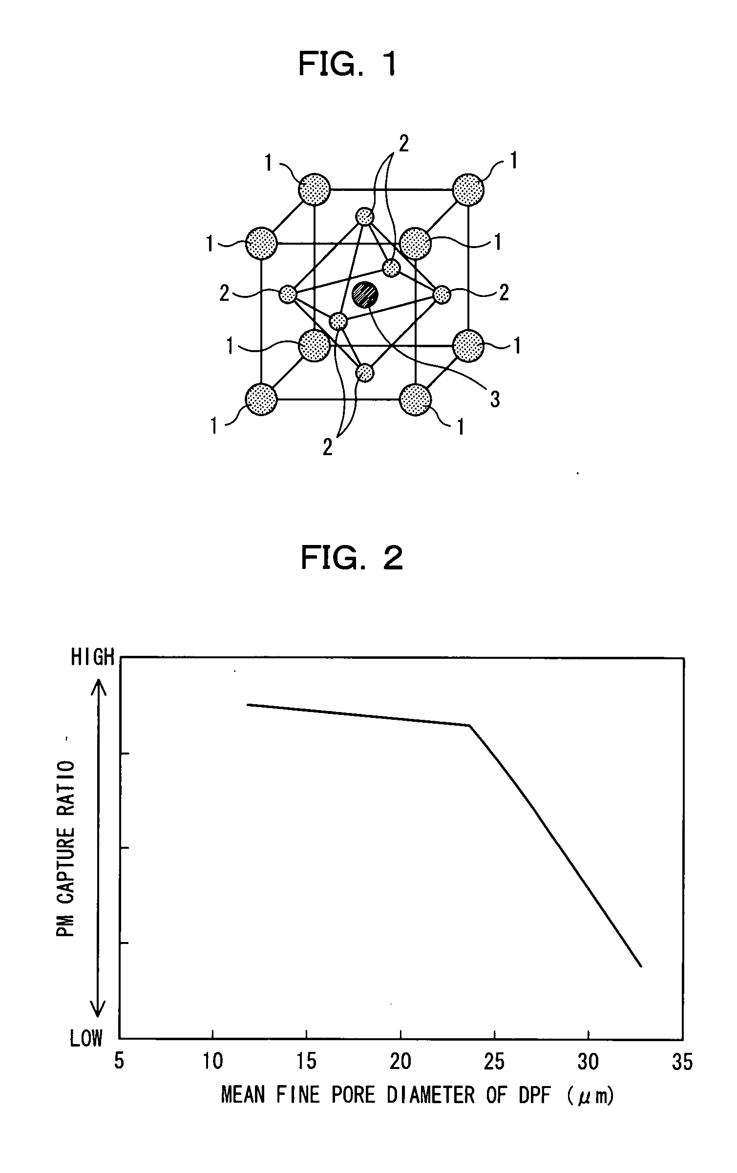
[0077] Each powder of perovskite type complex oxides after firing was mixed with simulated PM. For the simulated PM, carbon black (mean particle size: 2.09 μm) available...
example 8
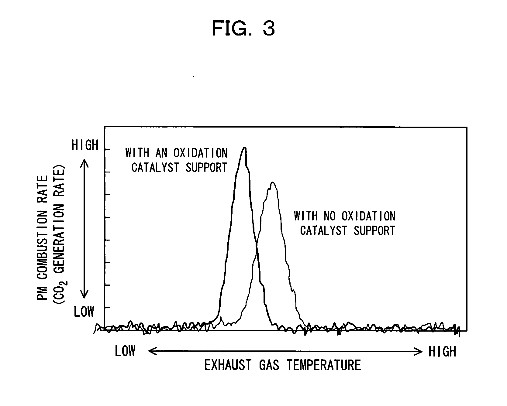
[0081] La0.8Ba0.2FeO3 which is a perovskite type complex oxide and the simulated PM were weighed to achieve the 6-to-1 mass ratio and 8.5 mg of the powder mixture was heated at 20° C. / min in the air atmosphere using a thermobalance and the combustion start temperature was obtained. FIG. 9 shows the results.
PUM
| Property | Measurement | Unit |
|---|---|---|
| pore diameter | aaaaa | aaaaa |
| pore diameter | aaaaa | aaaaa |
| particle size | aaaaa | aaaaa |
Abstract
Description
Claims
Application Information