Devices and methods for enrichment and alteration of cells and other particles

a technology of cell and particle, applied in the field of cell separation, medical diagnostics, microfluidic devices, can solve the problems of large volume of sample and skilled operators, low quantities, and large equipment costs, and achieve the effects of reducing the hydrodynamic size of a particle, increasing deformation, and decreasing volum

Inactive Publication Date: 2007-08-23
THE GENERAL HOSPITAL CORP +1
View PDF23 Cites 157 Cited by
  • Summary
  • Abstract
  • Description
  • Claims
  • Application Information

AI Technical Summary

Benefits of technology

[0009] In a fourth aspect, the invention provides a device for producing a sample enriched in red blood cells that includes an analytical device that enriches the red blood cells based on size, shape, deformability, or affinity; and a reservoir including a reagent that oxidizes iron, where the reagent (e.g., sodium nitrite) increases the magnetic responsiveness of the red blood cells. The analytical device may include a first channel that includes a structure that deterministically deflects particles having a hydrodynamic size above a critical size in a direction not parallel to the average direction of flow in the structure.
[0032] By “shrinking reagent” is meant a reagent that decreases the hydrodynamic size of a particle. Shrinking reagents may act by decreasing the volume, increasing the deformability, or changing the shape of a particle.
[0033] By “swelling reagent” is meant a reagent that increases the hydrodynamic size of a particle. Swelling reagents may act by increasing the volume, reducing the deformability, or changing the shape of a particle.

Problems solved by technology

Clinically or environmentally relevant information may often be present in a sample, but in quantities too low to detect.
For cells, different flow cytometry and cell sorting methods are available, but these techniques typically employ large and expensive pieces of equipment, which require large volumes of sample and skilled operators.
These methods often suffer from the inability to enrich a sample sufficiently to allow analysis of rare components of the sample.
Furthermore, such techniques may result in unacceptable losses of such rare components, e.g., through inefficient separation or degradation of the components.

Method used


Image

  • Devices and methods for enrichment and alteration of cells and other particles
  • Devices and methods for enrichment and alteration of cells and other particles
  • Devices and methods for enrichment and alteration of cells and other particles

Examples


example 1

A Silicon Device Multiplexing 14 3-stage Array Duplexes

[0241]FIGS. 42A-42E show an exemplary device, characterized as follows.

[0242] Dimension: 90 mm×34 mm×1 mm

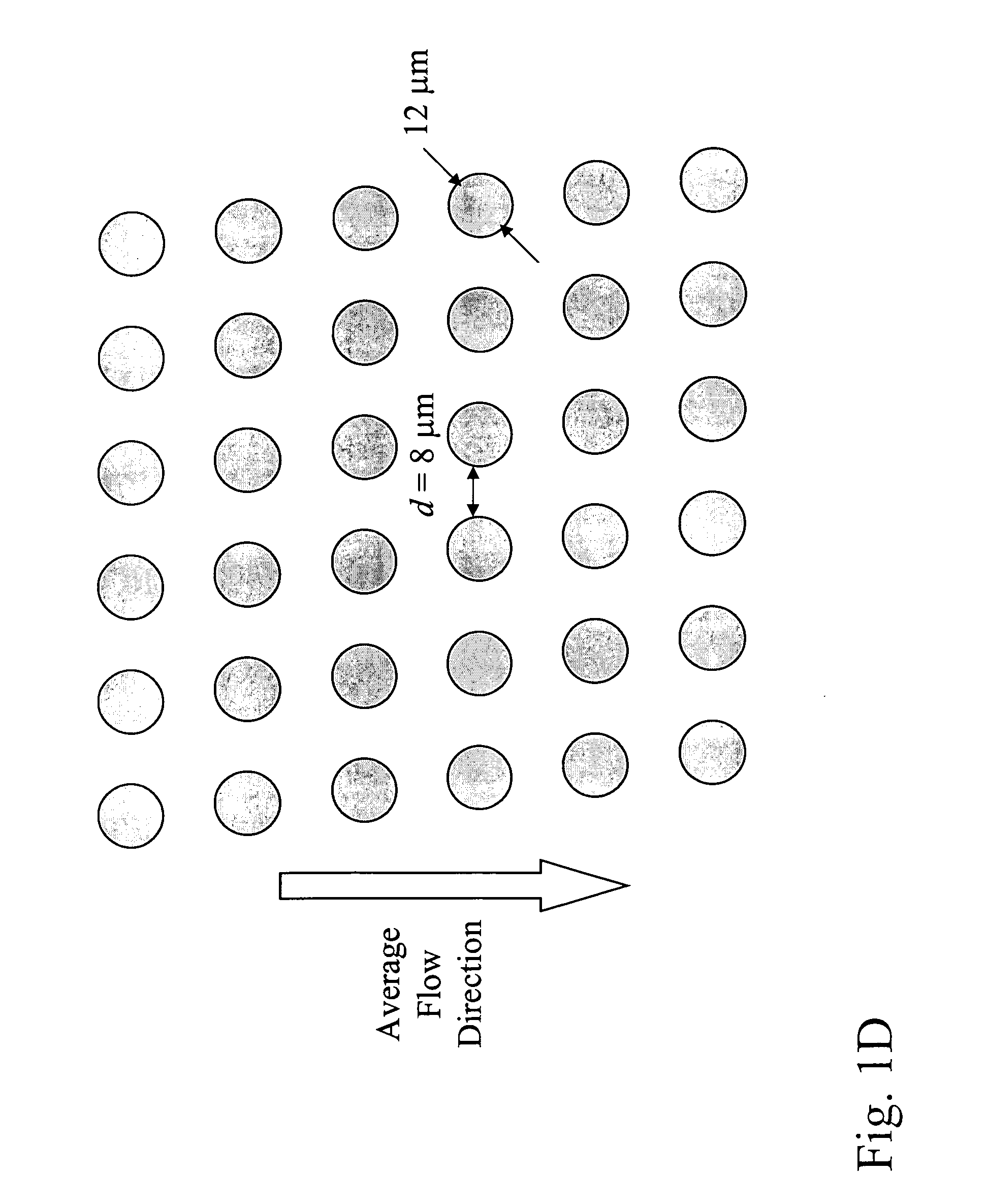
[0243] Array design: 3 stages, gap size=18, 12 and 8 μm for the first, second and third stage, respectively. Bifurcation ratio=1 / 10. Duplex; single bypass channel

[0244] Device design: multiplexing 14 array duplexes; flow resistors for flow stability

[0245] Device fabrication: The arrays and channels were fabricated in silicon using standard photolithography and deep silicon reactive etching techniques. The etch depth is 150 μm. Through holes for fluid access are made using KOH wet etching. The silicon substrate was sealed on the etched face to form enclosed fluidic channels using a blood compatible pressure sensitive adhesive (9795, 3M, St Paul, Minn.).

[0246] Device Packaging: The device was mechanically mated to a plastic manifold with external fluidic reservoirs to deliver blood and buffer to the device and extract the...

example 2

A Silicon Device Multiplexing 14 Single-Stage Array Duplexes

[0251]FIGS. 44A-44D show an exemplary device, characterized as follows.

[0252] Dimension: 90 mm×34 mm×1 mm

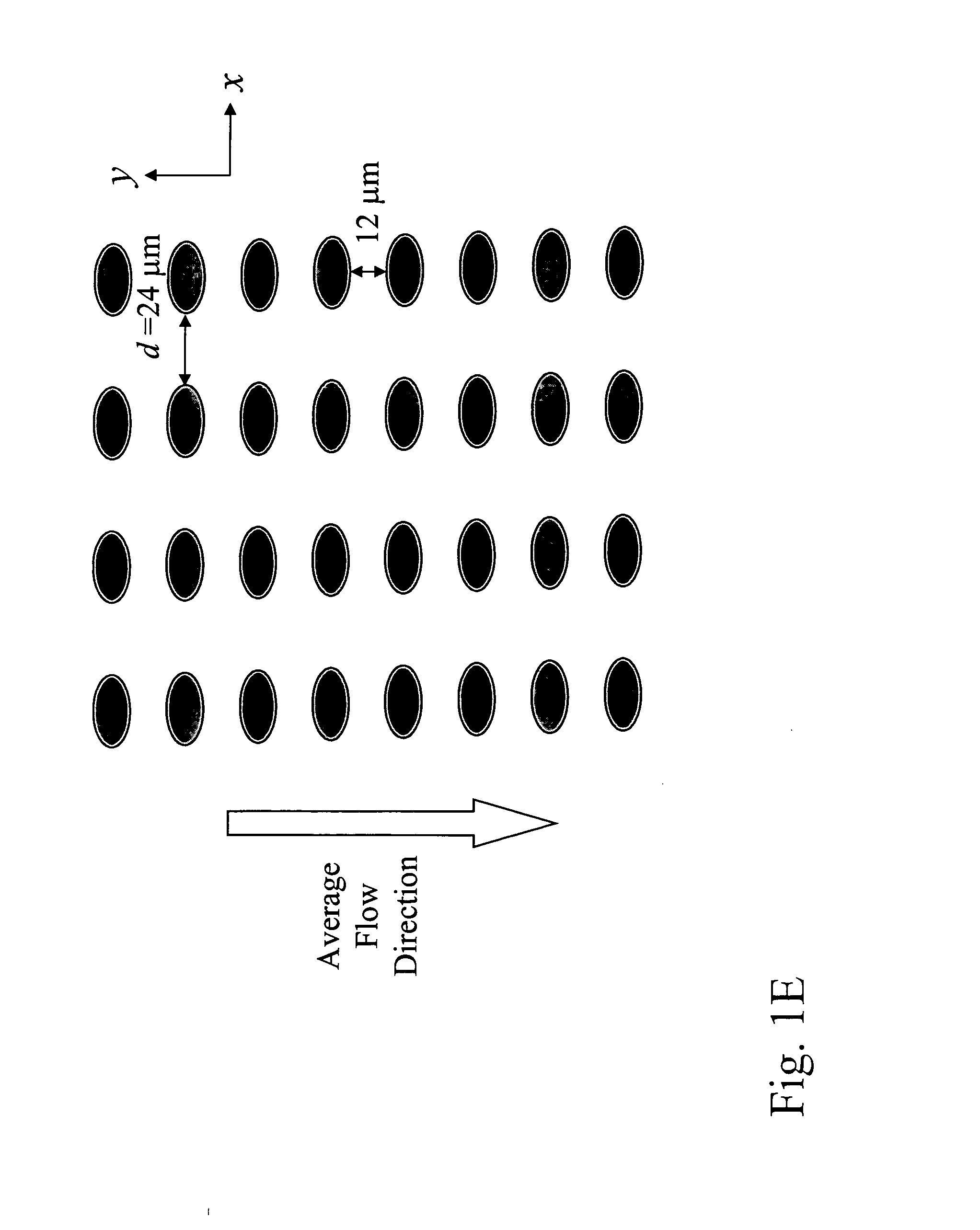
[0253] Array design: 1 stage, gap size=24 μm. Bifurcation ratio=1 / 60. Duplex; double bypass channel

[0254] Device design: multiplexing 14 array duplexes; flow resistors for flow stability

[0255] Device fabrication: The arrays and channels were fabricated in silicon using standard photolithography and deep silicon reactive etching techniques. The etch depth is 150 μm. Through holes for fluid access are made using KOH wet etching. The silicon substrate was sealed on the etched face to form enclosed fluidic channels using a blood compatible pressure sensitive adhesive (9795, 3M, St Paul, Minn.).

[0256] Device Packaging: The device was mechanically mated to a plastic manifold with external fluidic reservoirs to deliver blood and buffer to the device and extract the generated fractions.

[0257] Device Operation: An external...

example 3

Separation of Fetal Cord Blood

[0261]FIG. 45 shows a schematic of the device used to separate nucleated cells from fetal cord blood.

[0262] Dimension: 100 mm×28 mm×1 mm

[0263] Array design: 3 stages, gap size=18, 12 and 8 μm for the first, second and third stage, respectively. Bifurcation ratio 1 / 10. Duplex; single bypass channel.

[0264] Device design: multiplexing 10 array duplexes; flow resistors for flow stability.

[0265] Device fabrication: The arrays and channels were fabricated in silicon using standard photolithography and deep silicon reactive etching techniques. The etch depth is 140 μm. Through holes for fluid access are made using KOH wet etching. The silicon substrate was sealed on the etched face to form enclosed fluidic channels using a blood compatible pressure sensitive adhesive (9795, 3M, St Paul, Minn.).

[0266] Device Packaging: The device was mechanically mated to a plastic manifold with external fluidic reservoirs to deliver blood and buffer to the device and ext...


PUM

PropertyMeasurementUnit
thickaaaaaaaaaa
diameteraaaaaaaaaa
diameteraaaaaaaaaa

Abstract

The invention features a device for the deterministic separation of analytes coupled to a reservoir containing a reagent that alters a magnetic propert of the analyte. Exemplary methods include the enrichment of a sample in a desired analyte (e.g., using deterministic separation) or the alteration of a desired analyte in the device. The devices and methods may be advantageously employed to enrich for rare cells, e.g., fetal cells or epithelial cells, present in a sample, e.g., maternal blood.

Description

CROSS-REFERENCE TO RELATED APPLICATIONS [0001] The present application claims the benefit of U.S. Provisional Application Ser. Nos. 60 / 668,415, filed Apr. 5, 2005 and 60 / 704,067, filed Jul. 29, 2005, each of which is hereby incorporated by reference in its entirety.BACKGROUND OF THE INVENTION [0002] The invention relates to the fields of cell separation, medical diagnostics, and microfluidic devices. [0003] Clinically or environmentally relevant information may often be present in a sample, but in quantities too low to detect. Thus, various enrichment or amplification methods are often employed in order to increase the detectability of such information. [0004] For cells, different flow cytometry and cell sorting methods are available, but these techniques typically employ large and expensive pieces of equipment, which require large volumes of sample and skilled operators. These cytometers and sorters use methods like electrostatic deflection, centrifugation, fluorescence activated c...

Claims


Application Information

Patent Timeline
Patent Type & Authority Applications(United States)
IPC IPC(8): C12Q1/70G01N33/567C12M3/00
CPCB01L3/502746Y10T436/25B01L3/502761B01L2200/0647B01L2300/0816B01L2300/0864B01L2400/0406B01L2400/0409B01L2400/0415B01L2400/043B01L2400/0472B01L2400/0487B01L2400/086B03C1/30B03C1/32B03C2201/18C12M47/04C12M47/06G01N1/40G01N33/5044G01N2035/00237Y10T436/25375B01L3/502753B33Y80/00Y10T137/0318Y10T137/8593G01N30/0005G01N33/49G01N33/50C12Q1/686G01N1/4077
Inventor KAPUR, RAVITONER, MEHMET
Owner THE GENERAL HOSPITAL CORP
Why Eureka
Try Eureka