Sputter Deposition System and Methods of Use

Inactive Publication Date: 2007-09-13
VEECO INSTR
View PDF8 Cites 24 Cited by
  • Summary
  • Abstract
  • Description
  • Claims
  • Application Information

AI Technical Summary

Benefits of technology

[0011]In one example, the vacuum chamber is generally circular such that the chamber includes an azimuthal axis, and the transport mechanism further includes an arm rotatable about the azimuthal axis and a substrate holder attached to the arm at a radius from the azimuthal axis. The substrate holder supports the substrate at the radius as the arm rotates about the azimuthal axis to move the substrate holder to intersect the deposition zone and the treatment zone. The substrate holder may also be configured to spin about a central rotation axis for spinning the substrate as the arm transports the substrate through the deposition zone. In addition, a processor may be provided in communication with the transport mechanism, wherein the processor instructs the transport mechanism to rotate the arm about the azimuthal axis through the treatment and/or deposition zone(s) at least at desired first and second angular velocities. The different velocities provide for substantially uniform modification of the substrate surface and/or for a substanti

Problems solved by technology

These pressure and temperature changes may result in formation of undesirable interface layers on the processed substrate.
In addition, the sp

Method used


Image

  • Sputter Deposition System and Methods of Use
  • Sputter Deposition System and Methods of Use
  • Sputter Deposition System and Methods of Use

Examples


Embodiment Construction

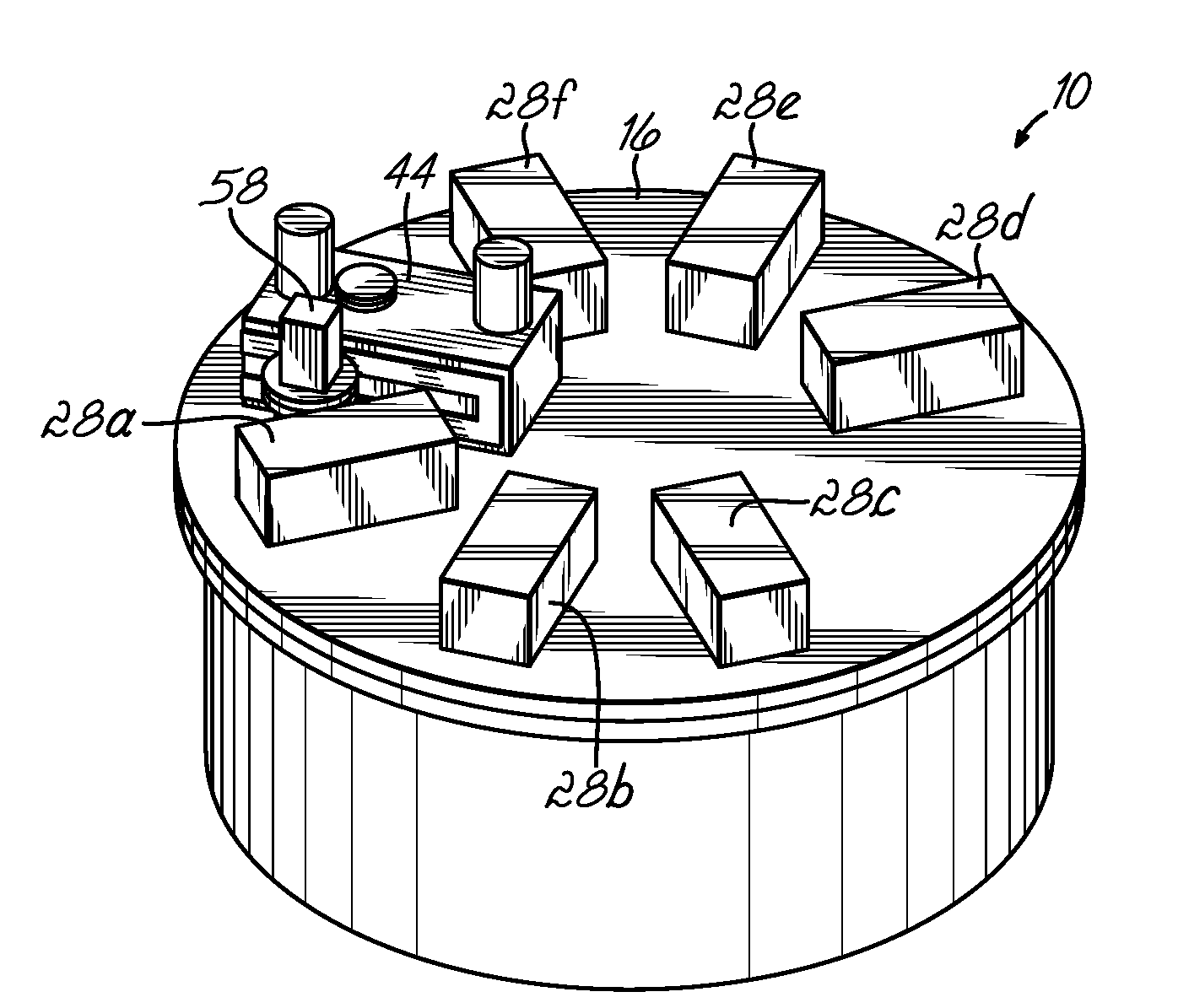
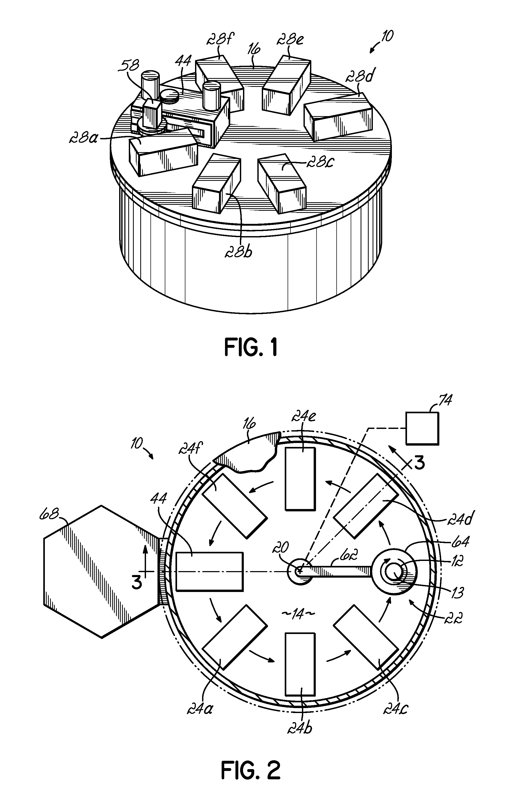
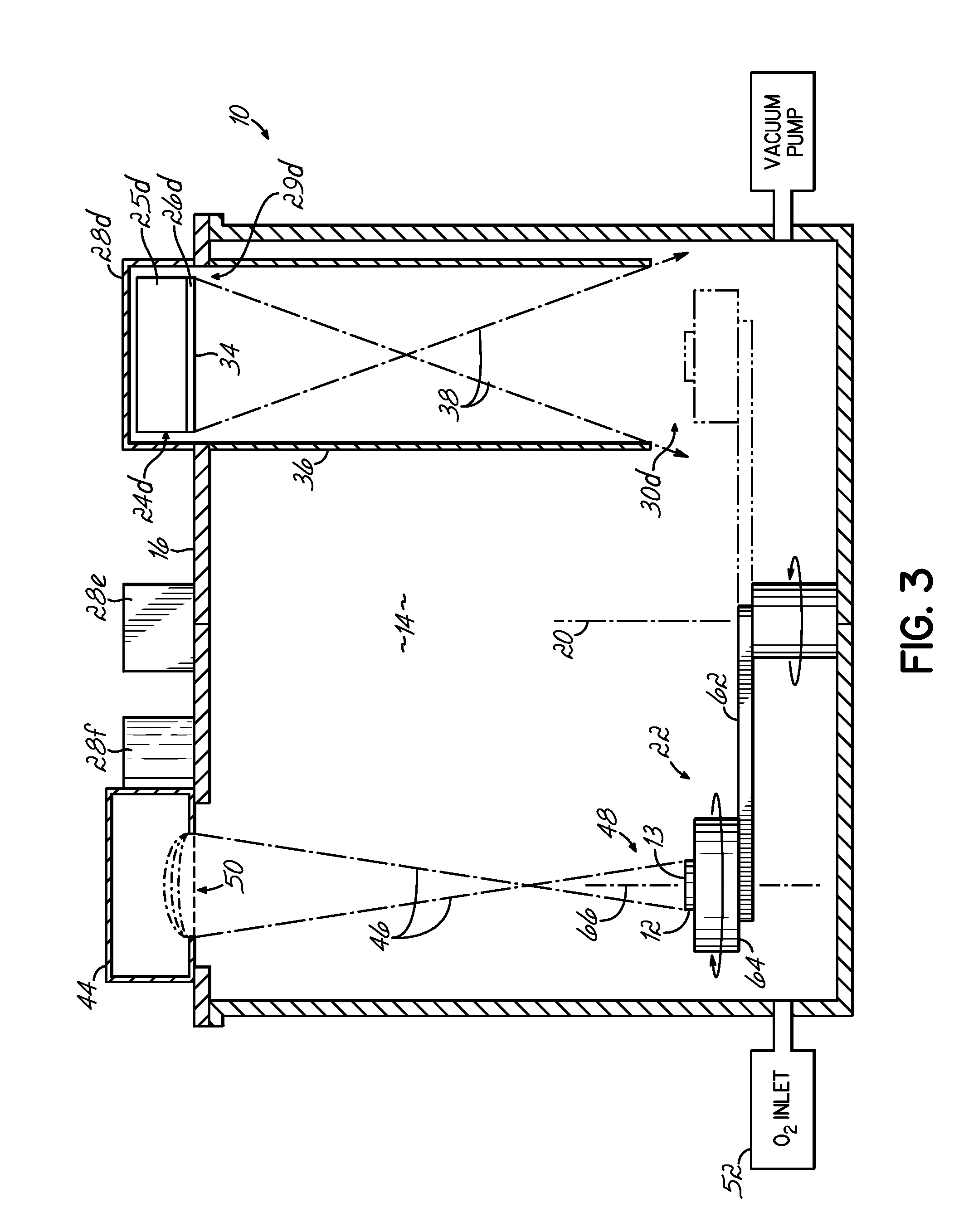
[0024]In accordance with one embodiment of the invention, as shown in FIGS. 1-4, a physical vapor deposition (PVD) system 10 is provided for forming one or more layers of a coating material 11a, 11b, 11c, 11d, 11e, 11f, 11g, and 11h on a substrate 12 and for treating, or modifying, the substrate surface, which can include the surface 13 of the substrate 12 surface or a deposited layer of coating material 11a-11h on the substrate 12. A control system (not shown), which has a construction understood by persons having ordinary skill in the art, orchestrates the operation of the PVD system 10.

[0025]The PVD system 10 includes a vacuum chamber 14 and a chamber lid 16 (shown in partial). The vacuum chamber 14 is generally circular in nature and includes an azimuthal axis 20 about which a transport mechanism 22 is configured to move the substrate 12. The vacuum chamber 14 further defines an evacuable or controlled atmosphere volume. Each of six physical vapor deposition sources, as represen...


PUM

PropertyMeasurementUnit
Thicknessaaaaaaaaaa
Radiusaaaaaaaaaa
Dimensionaaaaaaaaaa

Abstract

The present invention relates a physical vapor deposition (PVD) system. e.g. a planetary system, for forming one or more layers of a coating material on a substrate and for treating, or modifying, the substrate surface, which can include the surface of the substrate or a deposited layer of coating material thereon. The PVD system includes a single vacuum (or process) chamber having an ion source and at least one PVD source of the coating material. The ion source, such as a linear ion source, is configured to emit a beam of energetic particles at a substrate for surface modification of the substrate surface, for example, to provide film densification, etching, cleaning, surface smoothing, and/or oxidation thereof. The PVD source(s) of the coating material deposits one or more layers of coating material(s) on the substrate. The uniformity of substrate surface modification and the thickness uniformity of the deposited layers can be maintained by velocity profiling of the rotating substrate within the vacuum chamber.

Description

CROSS REFERENCE TO RELATED APPLICATIONS[0001]The present application is a continuation-in-part of U.S. patent application Ser. No. 11 / 372,517, filed Mar. 10, 2006, and titled “SPUTTER DEPOSITION SYSTEM AND METHODS OF USE”, the disclosure of which is hereby incorporated by reference herein in its entirety.FIELD OF THE INVENTION[0002]The present invention relates to a sputter deposition system for processing substrates, such as semiconductor wafers and data storage components, and, more particularly, to a system including an ion source and methods of use thereof for surface modification of substrates.BACKGROUND OF THE INVENTION[0003]Physical vapor deposition (PVD) modules or systems are used manufacturing sensor elements, for example, for spin-valve giant magnetoresistance (GMR) and tunneling magnetoresistance (TMR) read / write heads for the data storage industry and similar devices. With PVD, typically thin layers or films of magnetic and non-magnetic materials are stacked on a substr...

Claims


Application Information

Patent Timeline
IPC IPC(8): C23C14/32C23C14/00
CPCC23C14/352C23C14/5833C23C14/568C23C14/505
Inventor LEE, CHIH-LINGDEVASAHAYAM, ADRIANMAO, MING
Owner VEECO INSTR
Why Eureka
Try Eureka