Plasma Torch Spectrometer

a spectrometer and plasma torch technology, applied in mass spectrometers, particle separator tubes, isotope separation, etc., can solve the problems of toroidal or faulty plasma shape, glass tube melting, and torch destruction

Inactive Publication Date: 2007-09-27
GBC SCI EQUIP
View PDF7 Cites 18 Cited by
  • Summary
  • Abstract
  • Description
  • Claims
  • Application Information

AI Technical Summary

Benefits of technology

[0007] The object of the invention is to provide a spectrometer in which the torch is prot...

Problems solved by technology

The donut plasma tends to spread out and make contact with the glass tube, and this in turn results in melting of the glass tube which destroys the torch.
The main cause of the shape of the plasma snapping from the normal plasma shape to the toroidal or faulty shape is insufficient coolant gas flow which may be the result of a...

Method used


Image

  • Plasma Torch Spectrometer
  • Plasma Torch Spectrometer

Examples


Embodiment Construction

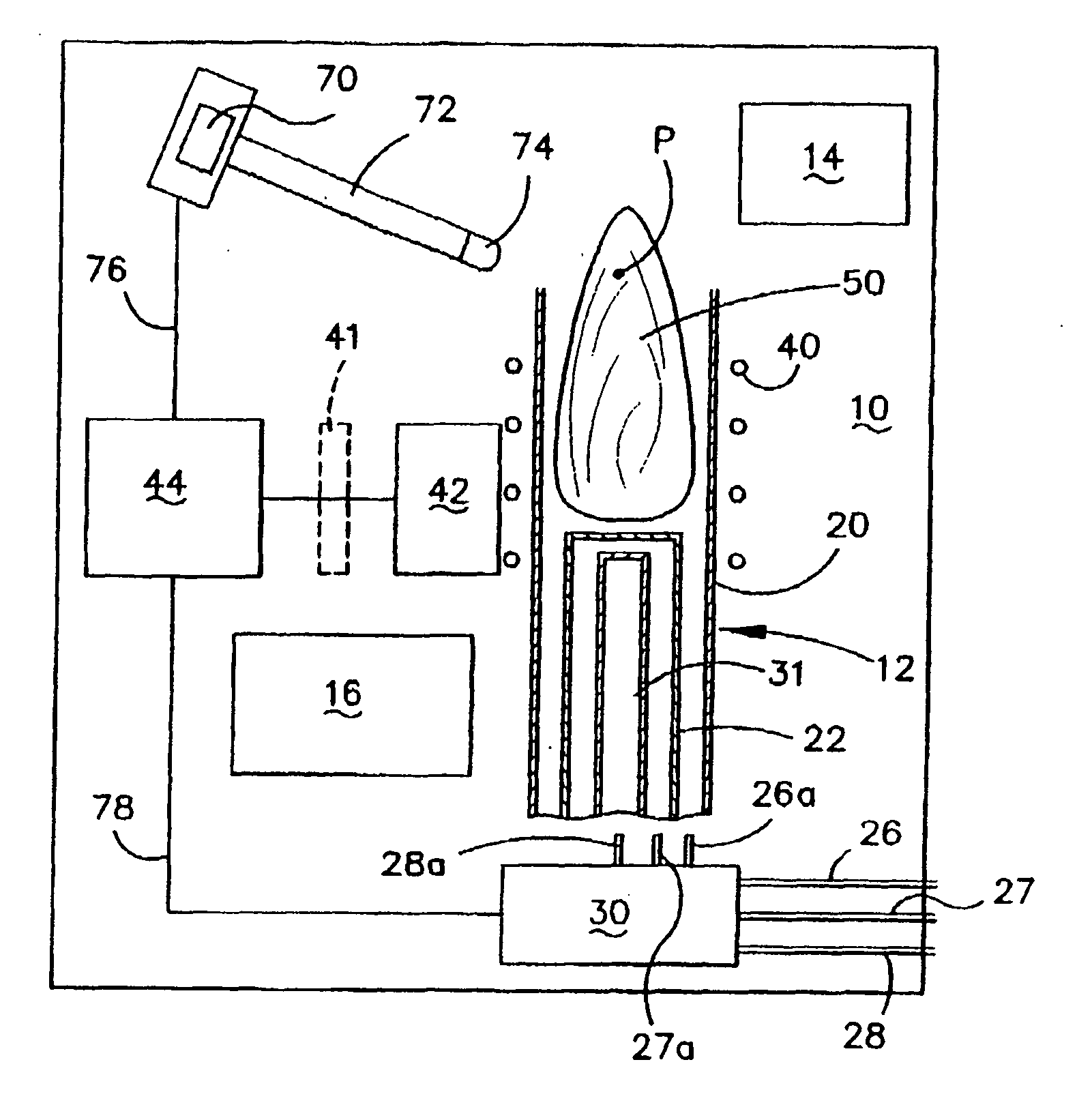
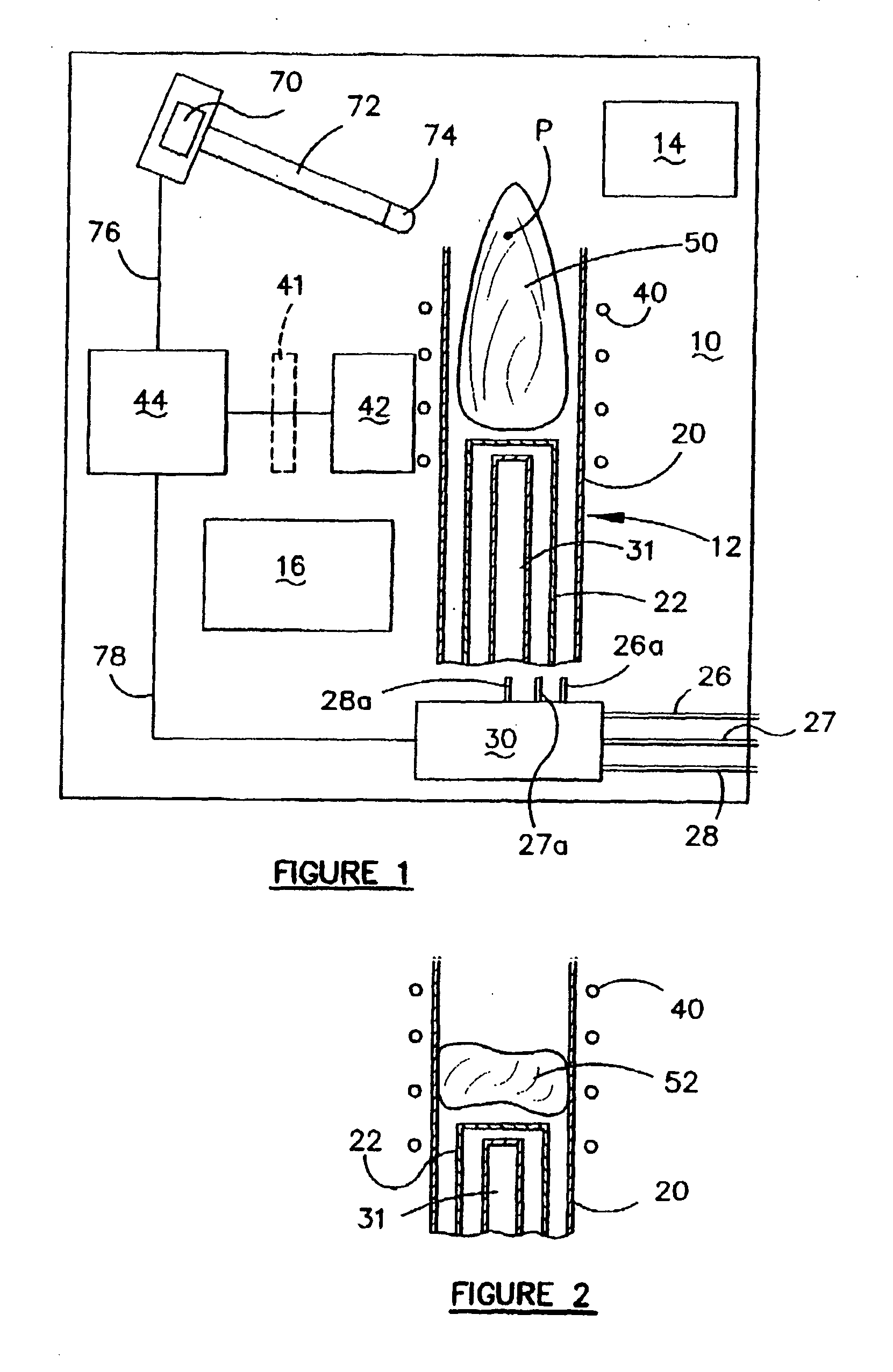
[0026] With reference to FIG. 1, a spectrometer 10 is schematically shown which uses an inductively coupled plasma torch 12 to create sample for analysis in the spectrometer 10. The spectrometer 10 is of conventional design and therefore is not described in detail, other than to say it will normally include a display 14 on which results can be displayed and a processing section 16 which controls the spectrometer and performs the analysis so that the results can be displayed on the display 14, or otherwise provided to an operator.

[0027] The plasma torch 12 has an outer tube 20 and an inner tube 22. Coolant or plasma gas is supplied from a coolant or plasma gas line 26 via one or more valves and flow control devices schematically shown at 30 to line 26a which supplies the coolant or plasma gas to the space between the outer tube 20 and inner tube 22. Auxiliary gas is supplied by line 27 through the valve and flow control section 30 to line 27a and then to the inner tube 22 and sample...


PUM

PropertyMeasurementUnit
Shapeaaaaaaaaaa
Electric potential / voltageaaaaaaaaaa
Light intensityaaaaaaaaaa

Abstract

A spectrometer is disclosed which comprises a plasma torch and an induction coil for generating a normal plasma within the torch. The torch has an outer tube and an inner tube. If the plasma collapses from a normal plasma state to a toroidal or faulty plasma shape, a photodiode detects the change in shape so that the plasma torch can be shut down to prevent the plasma shape from melting the tube of the torch.

Description

FEILD OF THE INVENTION [0001] This invention relates to an inductively coupled plasma torch spectrometer such as a time of flight mass spectrometer, quadrupole, UES spectrometer, or any other spectrometer which uses an inductively coupled plasma torch in order to produce sample for analysis. BACKGROUND ART [0002] Sample which is required to be analysed by various types of spectrometers is often provided by an inductively coupled plasma torch. Such torches receive a coolant or plasma gas together with an auxiliary gas and a sample carrier gas. The gases are usually argon and the torch is provided with a glass quartz outer envelope or tube (hereinafter referred to as a tube) about which an RF induction coil is provided. When the gases are supplied to the torch and the coil and an ignition spark device are activated, a plasma is created and the sample material in the carrier gas is ionised for analysis in the spectrometer. [0003] It has been found that when the plasma is created by the...

Claims


Application Information

Patent Timeline
IPC IPC(8): H05H1/30H01J49/36G01N21/00G01N21/73
CPCG01N21/73H05H1/30G01N2201/084
Inventor CONDICK, GEOFFREY MARK
Owner GBC SCI EQUIP
Why Eureka
Try Eureka