Carbon nanotube chain and production process for the same, target detector, and target detection method

a carbon nanotube and production process technology, applied in the field of carbon nanotube chain and production process for the same, target detector, and target detection method, can solve the problems of difficult to take a given number of carbon nanotubes and align them at regular intervals, not uniform in length, thickness, etc., and achieve high sensitivity and ease

Inactive Publication Date: 2007-10-11
FUJITSU LTD +2
View PDF36 Cites 22 Cited by
  • Summary
  • Abstract
  • Description
  • Claims
  • Application Information

AI Technical Summary

Benefits of technology

[0012] In the nanohole structure formation step of the process of the present invention, grooves are formed in a metallic layer, followed by nanohole formation treatment to the metallic layer. In this way, a nanohole structure is obtained in which rows of nanoholes that are oriented in a direction substantially orthogonal to the surface of the metallic layer are formed in the grooves. In the carbon nanotube formation step, carbon nanotubes are formed in the nanoholes. In the carbon removal step, carbon deposited on surfaces of lands of the metallic layer between the grooves in the carbon nanotube formation step is removed. In the metallic layer dissolving step, the metallic layer is dissolved away. Through these steps, the carbon nanotube chain of the present invention is efficiently produced.
[0013] The target detector of the present invention includes the carbon nanotube chain of the present invention and a holder, wherein the carbon nanotube chain includes a capturing portion capable of capturing a detection target. Since the carbon nanotube chain of the present invention in the target detector includes such a capturing portion, various types of detection targets can be captured by the capturing portion. Moreover, since the carbon nanotube chain is immobilized to the holder, the target detector can be operated by hand. When two or more of the carbon nanotube chains are immobilized to the holder, it is possible to impart different functions to each carbon nanotube chain, and further to impart different functions to different sets of carbon nanotubes in each carbon nanotube chain. Accordingly, the target detector of the present invention is capable of high-sensitivity detection, and qualitative and quantitative analysis, of various types of targets including disease-causing substances, biological substances and toxic substances, and can be suitably used in various fields including sensors such as biosensors and gas sensors.
[0014] The target detection method of the present invention includes causing the target detector of the present invention to act on a sample containing a detection target. Since the target detection method of the present invention involves use of the target detector of the present invention that includes the carbon nanotube chain of the present invention, various types of detection targets act on the carbon nanotubes. Accordingly, the detection target in the sample can be detected with high sensitivity and with ease. When the target detector has two or more of the carbon nanotube chains, it is possible to impart different functions to each carbon nanotube chain, and further to impart different functions to different sets of carbon nanotubes in each carbon nanotube chain. Accordingly, different detection targets can act on the carbon nanotube chains or carbon nanotubes, thereby allowing simultaneous analysis of multiple detection targets.

Problems solved by technology

Carbon nanotubes prepared by arc discharging or the like, however, are not uniform in length, thickness, etc., and are produced as discrete fine particles; therefore, it is difficult to take a given number of the carbon nanotubes and align them at regular intervals.
For this reason, this method cannot provide carbon nanotubes that are arranged regularly (e.g., in a row).

Method used


Image

  • Carbon nanotube chain and production process for the same, target detector, and target detection method
  • Carbon nanotube chain and production process for the same, target detector, and target detection method
  • Carbon nanotube chain and production process for the same, target detector, and target detection method

Examples


example 1

—Preparation of Carbon Nanotube Chain—

[0180] As shown in FIG. 3A, using an EB mask writer (ELS7000, manufactured by ELIONIX CO., LTD.), an EB resist was applied over a SiC substrate and lines were written to produce a pattern of concaves and convexes (lines and spaces), followed by etching treatment to obtain a SiC mold 50. Note that the interval (pitch) between adjacent concave lines (grooves) in the pattern was 150 nm, the depth of the grooves was 100 nm, and the ratio of the width of the convex or land to the width of the concave or groove, (convex width / concave width), was 1:1.

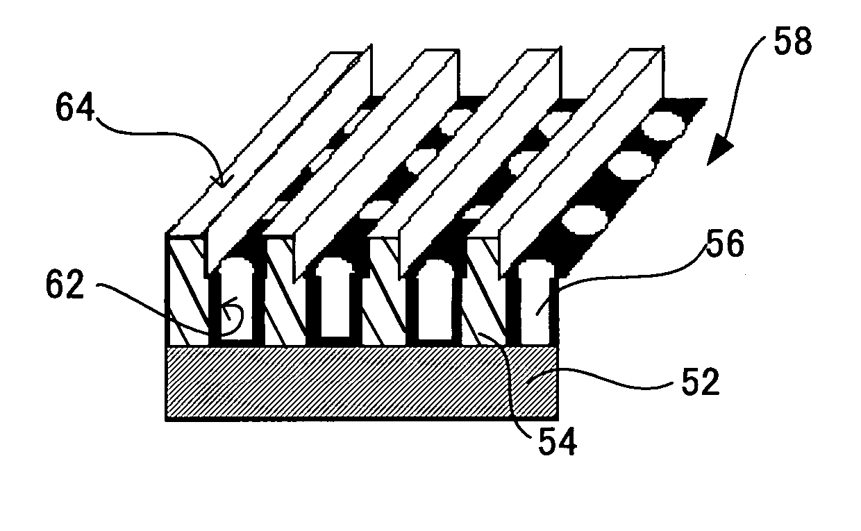
[0181] As shown in FIG. 3B, Nb was vacuum-deposited onto a silicon substrate 52 by sputtering to a thickness of 50 nm so as to form an electrode layer that is identical to that described above, and aluminum was vacuum-deposited onto the electrode layer to a thickness of 350 nm by sputtering of an aluminum sputtering target so as to form a metallic layer 54 identical to that described above. The SiC mold 5...

example 2

—Preparation of Carbon Nanotube Chain—

[0187] A carbon nanotube chain of Example 2 was prepared as in Example 1 except that the following carbon removal step was adopted.

[0188] The nanohole structure 58 having the carbon layer 60 deposited on its surface, obtained by the foregoing carbon nanotube formation step, was set to an oxygen ion beam system, wherein the ion source adopted in the system was a 20 kv ECR (Electron Cyclotron Resonance) source placed so that the incident angle of an ion beam was 45° with respect to the sample holder. As shown in FIG. 4, the nanohole structure 58 was then irradiated with a 500 eV oxygen ion beam 70 to remove the carbon layers 60 deposited on the surfaces of the lands 64 between the grooves, i.e., both the carbon layer deposited on the top surface of the lands 64 of the metallic layer 54 and the carbon layer deposited to the side surfaces of the lands 64 (see FIG. 3E).

[0189] Subsequently, as in Example 1, the metallic layer dissolving step was per...

example 3

—Preparation of Carbon Nanotube Chain—

[0190] A carbon nanotube chain of Example 3 was prepared as in Example 1 except that the following carbon removal step was adopted.

[0191] The nanohole structure 58 having the carbon layer 60 deposited on its surface, obtained by the foregoing carbon nanotube formation step, was set to an ion milling system (ME-1001, manufactured by Veeco Instruments). The nanohole structure 58 was then irradiated with an argon ion beam at an incident angel of 30° under the condition that the acceleration voltage was 50V and current density was 20 mA / cm2, to remove the carbon layers 60 deposited on the surfaces of the lands 64 between the grooves, i.e., both the carbon layer deposited on the top surface of the lands 64 of the metallic layer 64 and the carbon layer deposited to the sides of the lands 64.

[0192] Subsequently, as in Example 1, the metallic layer dissolving step was performed to provide a linear carbon nanotube chain 68 according to the present inve...


PUM

PropertyMeasurementUnit
lengthaaaaaaaaaa
thicknessaaaaaaaaaa
widthaaaaaaaaaa

Abstract

To provide a carbon nanotube chain consisting of a row of carbon nanotubes, the carbon nanotube chain being suitably used for instance as a target detector or sensor, and an efficient production process for the same. The carbon nanotube chain includes a support, and a plurality of carbon nanotubes bonded at one end to a surface of the support, wherein the plurality of carbon nanotubes is oriented in a direction substantially orthogonal to the surface of the support.

Description

CROSS-REFERENCE TO RELATED APPLICATIONS [0001] This application is based upon and claims the benefits of the priority from the prior Japanese Patent Application No. 2006-100656 filed on Mar. 31, 2006, the entire contents of which are incorporated herein by reference. BACKGROUND OF THE INVENTION [0002] 1. Field of the Invention [0003] The present invention relates to a carbon nanotube chain consisting of a row of carbon nanotubes, a production process for the carbon nanotube chain, a target detector using the carbon nanotube chain, and a target detection method using the target detector. [0004] 2. Description of the Related Art [0005] Carbon nanotubes (hereinafter may be referred to “CNT”) have been used as novel materials in various fields including electronics and electrics industries, and have been produced for instance by arc discharging, laser vaporization, thermal chemical vapor deposition (thermal CVD) or plasma chemical vapor deposition (plasma CVD). Known carbon nanotubes pr...

Claims


Application Information

Patent Timeline
Patent Type & Authority Applications(United States)
IPC IPC(8): D01F9/12
CPCB81B2201/0214B81C1/00206B81B2203/0361
Inventor ITOH, KEN-ICHIMASUDA, HIDEKIKYOTANI, TAKASHI
Owner FUJITSU LTD
Why Eureka
Try Eureka