
Reaction Vessel

a technology of reaction vessel and coupling parts, which is applied in the field of reaction vessel used, can solve the problems of complicated control, troublesome operation of coupling coupling parts, and complicated operation of assay instruments, and achieve the effects of preventing second pollution, simple structure and preventing secondary pollution

Inactive Publication Date: 2007-10-11
ITOHAM FOODS
View PDF3 Cites 5 Cited by
  • Summary
  • Abstract
  • Description
  • Claims
  • Application Information

AI Technical Summary

Benefits of technology

[0009] In accordance with this disclosure, the disclosed reaction vessel does not necessitate the coupling parts for the simplification of the assay instrument by adopting the structure that holds therein a sample liquid, reagent liquid, or washing liquid to be poured into the narrow tube; and permits direct photometry just by its set on the photometric equipment by providing a mechanism for controlling flow velocity of the liquid in the narrow tube; and makes its control easy by omitting a pump.
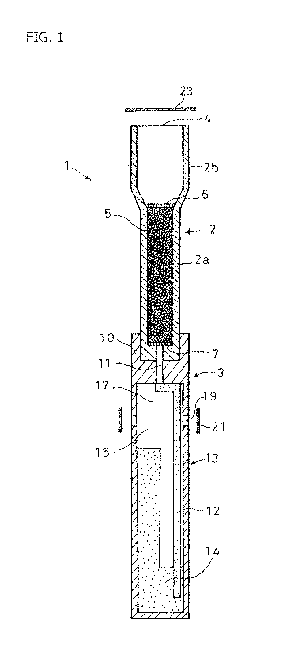
[0011] In such a reaction vessel, it is preferable that said current-controlling mechanism comprises at least control of liquid sucking force of said liquid absorbing member, and control of flow velocity in said communicating passage. It is also advantageous that said liquid absorbing member comprises a liquid-holding member for holding the absorbed liquid, and an directing member which connects said liquid-holding member to said communicating passage in order to direct to the liquid-holding member the liquid that flows from the communicating passage. Further, it is better that a free space is formed at the upstream of the region where the liquid-holding member is located in said effluent collecting tube. And, it is advantageous that a venting hole is formed at the upstream of the region where the liquid-holding member is located in said effluent collecting tube. Also it is preferable that said venting hole is sealable with a sealing member, or that said liquid feed port is sealable with a sealing member. Further it is better that said liquid absorbing member shows endothermic effect when it absorbs aqueous liquid. Advantageously, the reaction vessel of the present invention is disposable. Preferably, the narrow tube is packed with the solid phase support microparticles. Most advantageously, the reaction vessel of the present invention is used for immunoassay, and the reagent is any one of an antibody or antigen.
[0012] According to the disclosed reaction vessel, a sample liquid, washing liquid, labeled antibody liquid, or reaction reagent such as luminescent substrate, colorimetric substrate, or fluorescent substrate is poured into a narrow tube that is packed with solid phase support microparticles under various assays methods, thereby inducing luminescence or coloration inside the narrow tube that is packed with solid phase support microparticles. Therefore, measurement of its coloration amount, absorption of light, fluorescence intensity, etc, allows a substance to be identified or determined in the sample liquid.
[0013] The disclosed reaction vessel adopts the structure in which the liquid absorbing member absorbs the liquid being poured into the narrow tube, and thus collects it within the effluent collecting tube to prevent second pollution. Therefore, it is not necessary to build a tank outside the reaction vessel with the aim of prevention of secondary pollution. In addition to the tank, coupling parts for connecting the tank or photometric equipment to the reaction vessel would be unnecessary. Thus it is possible to adopt a simple structure, and also connecting operation for prevention of second pollution would be unnecessary, thereby enabling the measurement to be easily performed.
[0014] Also, the disclosed reaction vessel controls liquid current in the narrow tube by means of current-controlling mechanism, so that the adjustment of the sucking force is unnecessary, thereby facilitating the control. Additionally, any exterior sucking means such as a pump or means for controlling the current to the photometric equipment would be unnecessary, thus allows adoption of further simple structure.

Problems solved by technology

Further, a pump or aspirator would be needed for aspirating the liquid and generating liquid current, thus complicating the assay instrument.
Also, the operation for connecting the coupling parts has been troublesome.
Further, pouring of the liquid into the narrow tubes, or its flowing is performed by means of liquid pressure or sucking force through the pump or aspirator, so this has problems of difficult adjustment of liquid current and complicated control.

Method used


Image

  • Reaction Vessel
  • Reaction Vessel
  • Reaction Vessel

Examples


first embodiment

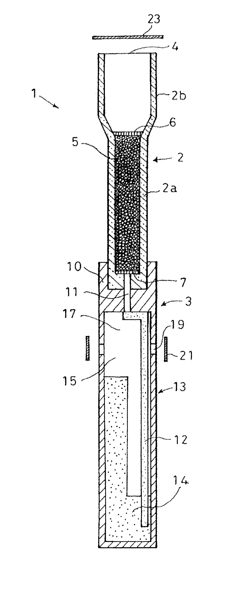
[0033]FIG. 1 shows reaction vessel 1 according to the present invention, which is equipped with narrow tube 2, and effluent collecting tube 3, and which includes current-controlling mechanism. This reaction vessel 1 is used for immunoassay, and is disposable, and can be put on the shelf by being directly subject to autoclave procedure or incineration, etc. after use in immunoassay. Immunoassay methods which are applicable to the reaction vessel 1 according to this embodiment, can include any methods provided that they can determine an antigen (including hapten antigen) or antibody to be measured, qualitatively, or quantitatively, or semiquantitatively be means of immune reaction. The immunoassay methods can specifically include, EIA: Enzyme Immunoassay such as ELISA: Enzyme-linked Immunosorbent Assay, FEIA: Fluorescent Enzyme Immunoassay, CLEIA: Chemiluminescent Enzyme Immunoassay, BLEIA: Bioluminescent Enzyme Immunoassay; or without any enzyme, FIA: Fluorescent Immunoassay, CLIA: C...

second embodiment

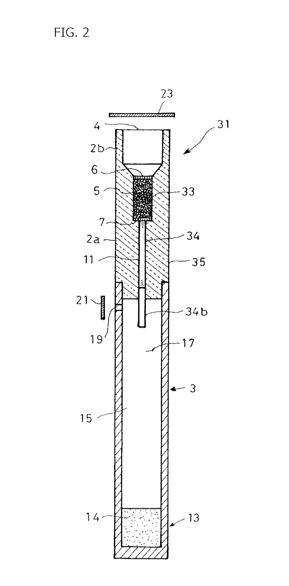
[0055]FIG. 2 shows reaction vessel 31 according to the This embodiment also includes narrow tube 2, and effluent collecting tube 3 which is connected to the lower end of narrow tube 2, and current-controlling mechanism. In this case, narrow tube 2 and effluent collecting tube 3 are approximately the same in outer diameter, and they do not have unevenness on the external surface, so the handleability and self life are improved.

[0056] Narrow tube 2 is composed of main body part 2a as enzymatic reaction site and measurement site, and liquid feed part 2b that is provided on the upper end of main body part 2a in an integrated fashion, and the whole is formed out of translucent material. Microparticles collecting station 33 is formed above main body part 2a of narrow tube 2, and this microparticles collecting station 33 is packed with solid phase support microparticles 5 which is similar to the first embodiment. At the upper and lower ends of microparticles collecting station 33, provide...


PUM

PropertyMeasurementUnit
lengthaaaaaaaaaa
diameteraaaaaaaaaa
diameteraaaaaaaaaa

Abstract

Reaction vessel 1 for assaying of a subject substrate molecule comprises a translucent narrow tube 2 which has a liquid feed port 4 at one end, and which is intended to be packed with microparticles 5 as solid phase support on which a reagent molecule is bound thereto, in which said reagent is capable of binding to, adsorbing, or showing affinity with the subject substrate molecule, and a effluent collecting tube 3 in which a liquid absorbing member 13 is provided inside for absorbing the liquid poured into the narrow tube, and which is connected to the narrow tube 2 at its downstream via a communicating passage 11, and a current-controlling mechanism for controlling liquid current in the narrow tube so as to hold the liquid in the narrow tube 2 during a predetermined time.

Description

FIELD OF THE INVENTION [0001] The present invention relates to a reaction vessel used for assay, in particular immunoassay method. BACKGROUND ART [0002] Immunoassay method makes use of antigen-antibody reaction, and is used for detection or quantitative determination of various substrates. This immunoassay method is broadly divided into competitive reaction method, and anti-competitive reaction method. Each method is divided into heterogeneous method which BF-separates antigen-antibody reaction bound form (B: Bound Form) from non-bound free form (F: Free Form), and homogeneous method which does not involve BF separation. The heterogeneous method includes liquid phase method where antigen-antibody reaction proceeds in liquid phase, and solid phase method where it proceeds in the interface between solid phase and liquid phase. For the determination of antigen or antibody, anti-competitive reaction method, in particular heterogeneous-solid phase method such as sandwich method, would ap...

Claims


Application Information

Patent Timeline
Patent Type & Authority Applications(United States)
IPC IPC(8): G01N33/53C12M3/00
CPCB01L3/50273G01N33/54366B01L2200/0621B01L2200/0631B01L2200/0689B01L2300/0681B01L2300/069B01L2300/0832B01L2300/126B01L2300/1877B01L2300/1894B01L2400/0406B01L2400/0457B01L2400/0694B01L2400/084B01L3/502746Y10S435/81Y10S436/81G01N33/543G01N33/53G01N33/68
Inventor MIYAKAWA, JUNJIMATSUMOTO, ASAMIOKA, SHUSAKU
Owner ITOHAM FOODS
Learn More