
Method of Spray Application of Monolithic Refractory, Spray Material for Use Therein, and Application Apparatus

a monolithic refractory and spraying technology, applied in the direction of lining repair, ceramic shaping core, chemical/physical processes, etc., can solve the problems of structural complexity and cost, need for being equipped with a kneading device and a slurry pressure feeding device which are structurally complicated and costly, and monolithic refractory material is sprayed, etc., to achieve excellent kneading effect, reduce variation, and low amount of application

Inactive Publication Date: 2007-10-18
KROSAKI HARIMA CORP
View PDF11 Cites 12 Cited by
  • Summary
  • Abstract
  • Description
  • Claims
  • Application Information

AI Technical Summary

Benefits of technology

[0016] In view of the above problems in the conventional dry spray application method which comprises adding water at a spray-material feed pipe, it is an object of the present invention to a spray application method, a spray material for use in the method, and a spray application apparatus, capable of avoiding attachment of a spray material on an inner surface of the spray-material feed pipe while increasing a kneading effect between water and the spray material, so as to obtain a low water-content, dense spray-applied product and facilitate enhanced operation efficiency.

Problems solved by technology

At the same time, the wet application method has disadvantages of the need for being equipped with a kneading device and a slurry pressure-feeding device which are structurally complicated and costly, and a time-consuming post-spraying operation of cleaning the slurried monolithic refractory material attached on the kneading device and an inner surface of a feed hose.
However, the monolithic refractory material, i.e., a spray material, is sprayed without allowing the water to be sufficiently mixed therewith.
Thus, a large amount of dust (coarse particulate) is generated during the spraying, and a refractory structure of a spray-applied product is apt to become nonuniform, to cause deterioration in deposit efficiency, bonding strength and corrosion resistance.
Moreover, the dry application method has a disadvantage of difficulty in obtaining a dense spray-applied product due to lower kneading (or mixing) effect and the use of a larger amount of water as compared with the wet application method.
While this method would be really effective in reducing an amount of dust generation and suppressing an attachment of the spray material on the inner surface of the hose as compared with the case of adding water only at the spray nozzle, an adequate kneading effect cannot be obtained because the spray material is hardly evenly wetted with water if it is simply sprayed.
Therefore, this technique could not provide a denser spray-applied product with lower water content as compared with the conventional dry application method.
This makes it difficult to evenly disperse the water in the spray material and obtain a sufficient kneading effect.
Therefore, this spray application method has a problem of difficulty in obtaining a dense spray-applied product.
While it is contemplated to arrange the watering device at a position distant from the spray nozzle so as to improve the kneading effect, a feed hose will be likely to cause clogging and a time for the cleaning operation will be increased.
However, in an actual test based on this method, it was found that, when the entire amount of application water is simply injected at an intermediate position of a feed pipe, a kneaded state becomes insufficient due to a poor affinity of water for the refractory powder, particularly, ultrafine powder materials therein, to cause an increase in rebound loss and an amount of dust generation and deterioration in workability (i.e., decrease in working-consistency), which leads to an disadvantage of hardly obtaining a spray-applied product with stable quality.
This causes a problem about a local variation in water content of a spray-applied product.
Specifically, a region with an excessively large water content of a spray-applied product has a high porosity, and conversely a region with an excessively small water content of a spray-applied product has an insufficient binding.
As the result, a desired durability cannot be obtained in both the regions.
Moreover, if the application water is added at a position distant from a nozzle hole, the spray material starts aggregating due to melt of the accelerator, to causes problems about the need for increasing an amount of application water, and an increase in time for the bothersome operation of cleaning the feed pipe.
This water is added to aim for a dust-generation protection effect, and therefore a preliminary kneading effect cannot be adequately obtained by adding such an amount of water.

Method used


Image

  • Method of Spray Application of Monolithic Refractory, Spray Material for Use Therein, and Application Apparatus
  • Method of Spray Application of Monolithic Refractory, Spray Material for Use Therein, and Application Apparatus
  • Method of Spray Application of Monolithic Refractory, Spray Material for Use Therein, and Application Apparatus

Examples


example 1

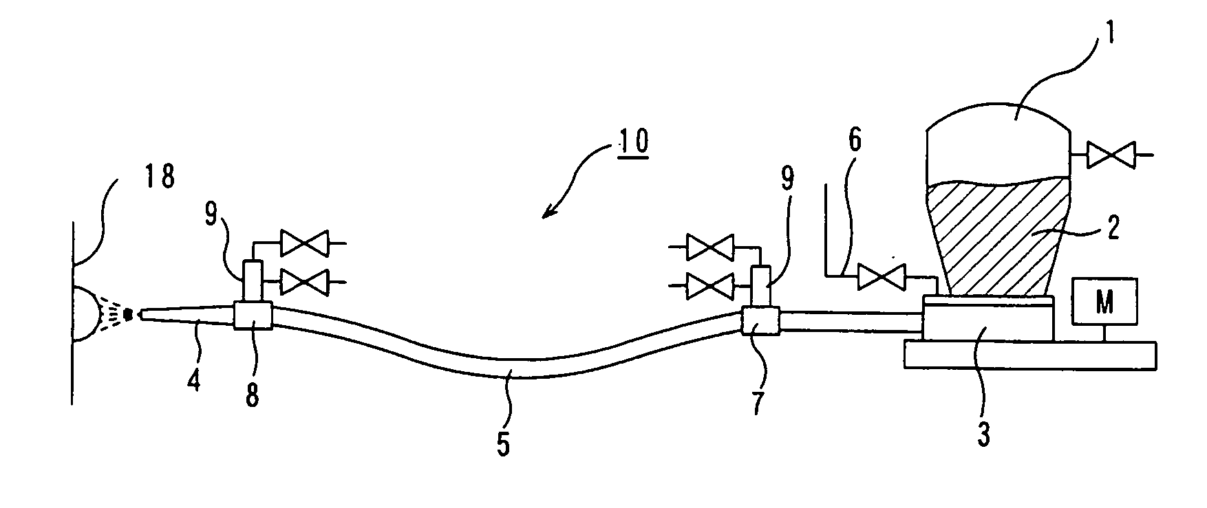
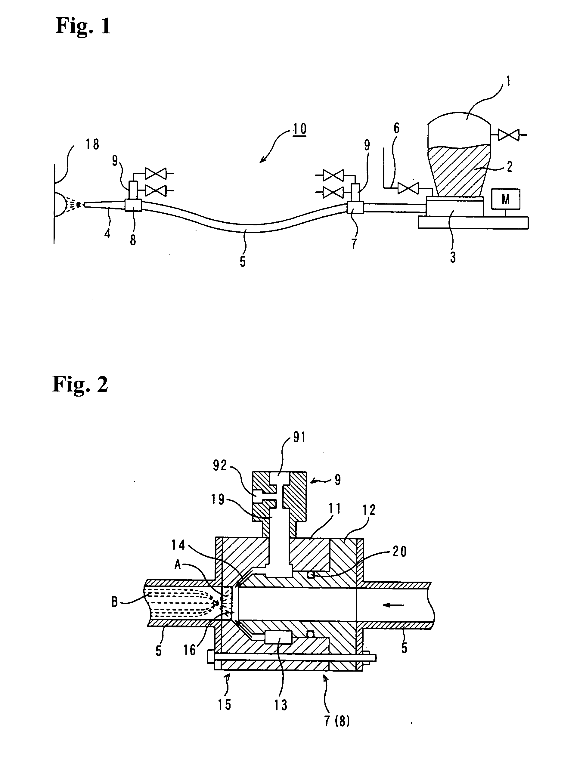
[0073]FIG. 1 generally shows an apparatus 10 using a spray application method for a monolithic refractory material according to the present invention.

[0074] In FIG. 1, the reference numeral 1 indicates a spray-material supply device containing a spray material 2. The spray-material supply device 1 may be any type used in a conventional spray application apparatus for a monolithic refractory material and adapted to quantitatively discharge a spray material therefrom, such as a rotektor gun, a lead gun and a nogami cement gun.

[0075] The spray-material supply device 1 is designed to be supplied with compressed air so as to adjust an inner pressure thereof, and provided with a table feeder 3 adapted to be driven by a motor M disposed at a lower end thereof. The table feeder 3 is operable to discharge the spray material 2 contained in the spray-material supply device 1 into a feed hose 5 extending from the spray-material supply device 1 to a distal spray nozzle 4.

[0076] Carrier air is...


PUM

PropertyMeasurementUnit
Temperatureaaaaaaaaaa
Lengthaaaaaaaaaa
Fractionaaaaaaaaaa

Abstract

Disclosed is a method and apparatus for spray application of a monolithic refractory material, designed to add water to a powder material and knead the powder material during feeding. In the method and apparatus, a primary water injector 7 is arranged in a feed hose 5 extending from a spray-material supply device 1 to a distal spray nozzle 4, and a secondary water injector 8 is arranged in the feed hose at a position just before the distal spray nozzle 4. The primary water injector 7 is arranged on an upstream side of the secondary water injector 8 with a given distance therebetween. 10 to 50 mass %, preferably 15 to 40 mass %, of application water on the basis of the total application water required for the spray application is added from the primary water injector together with compression air in the form of water particles having an average particle size of 100 μm or less, to evenly wet a spray material during feeding to the extent capable of preventing the spray material from being slurried. Then, the remaining application water is injected from the secondary water injector together with compression air. The spray application method and apparatus of the present invention can achieve a high kneading effect by a low amount of application water while improving operational efficiency.

Description

TECHNICAL FIELD [0001] The present invention relates to a method for spray application of a monolithic refractory material, during building or repairing of various types of metal containers and kilns, such as a blast furnace, a trough, a torpedo car, a converter, a ladle, a secondary refining furnace, a tundish, a cement rotary kiln, a waste melting furnace, an incinerator or a nonferrous metal container. The present invention also relates to a spray material for use in this method, and an application apparatus. BACKGROUND ART [0002] A method for spray application of a monolithic refractory material can be roughly classified into a wet application method and a dry application method. [0003] In the wet application method, a monolithic refractory material slurried by adding application water to a raw material and kneading (or mixing) them is pressure-fed (i.e., fed under pressure), and sprayed together with an accelerator (i.e., set accelerating agent) or the like added thereto in a d...

Claims


Application Information

Patent Timeline
IPC IPC(8): C04B35/66B05B17/04C04B28/06C04B28/26C04B28/34C04B35/117C04B35/443C04B35/63F27D1/16
CPCB01F5/0646C23C24/04B05B7/1431C04B28/06C04B28/26C04B28/34C04B35/117C04B35/443C04B35/6263C04B35/62665C04B35/63C04B35/6303C04B35/6316C04B35/632C04B35/66C04B2111/00146C04B2111/00551C04B2111/763C04B2235/3206C04B2235/3208C04B2235/3217C04B2235/3222C04B2235/3427C04B2235/3826C04B2235/402C04B2235/422C04B2235/5212C04B2235/5427C04B2235/5436C04B2235/5463C04B2235/77C04B2235/96F27D1/1636B01F5/0652C04B14/324C04B16/0675C04B20/008C04B22/0093C04B22/064C04B40/0028C04B40/0046C04B2103/408C04B14/30C04B20/0048C04B22/066C04B22/142B01F25/4335B01F25/433F27D1/16
Inventor OHATA, HIROKITOMONO, HIROYOSHIKAWAHARA, TOYOHIKOMIZUMA, YOSHIHIROGODA, KOJINISHIUMI, YOSHINORISHIRAMA, NORIKAZU
Owner KROSAKI HARIMA CORP
Learn More