
Method and System for Manufacturing Sintered Rare-Earth Magnet Having Magnetic Anisotropy

Active Publication Date: 2007-10-25
DAIDO STEEL CO LTD
View PDF10 Cites 44 Cited by
  • Summary
  • Abstract
  • Description
  • Claims
  • Application Information

AI Technical Summary

Benefits of technology

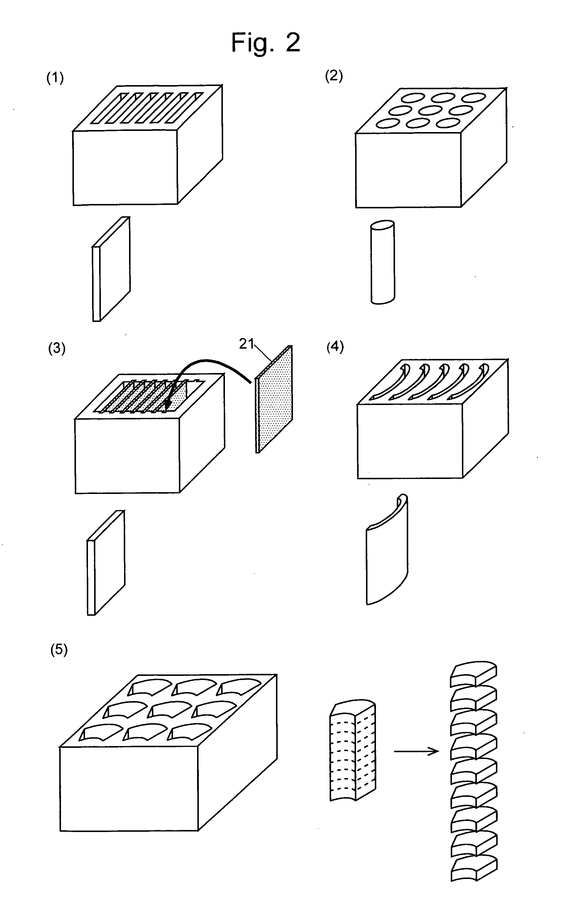
[0209] The present invention has been discovered as a technique for solving various problems and contradictions found in the conventional methods for manufacturing a sintered magnet having a magnetic anisotropy, such as RFeB, RCo and other rare-earth magnets. According to the present invention, it is unnecessary to use large-scale molding equipment, such as a die-pressing machine. Since there is no need to create a durable powder compact for handling, the misorientation never occurs and the resultant sintered magnet having a magnetic anisotropy has a net shape. Even if neither Tb nor Dy is used, it is possible to create a rare-earth magnet having a high coercive force by applying a strong, pulsed magnetic field through the air-core coil and by using a fine powder having a small grain size with low oxygen content, which can be produced by treating a chemically active fine powder containing a rare-earth element while preventing the powder from being in contact with air. It is also possible to efficiently produce high-performance magnets having the most widely produced shapes for commercial rare-earth magnets, such as the thin plate and arched plate types.

Problems solved by technology

However, these methods are inferior to the sintering method with respect to both the magnetic characteristics and productivity.
However, it also lowers the saturation magnetization and accordingly decreases the maximum energy product.
Furthermore, both Dy and Th are rarely found in nature and also expensive, so that these elements cannot be used to produce motors for hybrid cars, which will gain more commercial demand in the future, or other industrial or domestic motors.
The die-pressing method can apply the pressure only in one direction, which leads to misorientation.

Method used


Image

  • Method and System for Manufacturing Sintered Rare-Earth Magnet Having Magnetic Anisotropy
  • Method and System for Manufacturing Sintered Rare-Earth Magnet Having Magnetic Anisotropy
  • Method and System for Manufacturing Sintered Rare-Earth Magnet Having Magnetic Anisotropy

Examples


embodiments

[0234] [Mold]

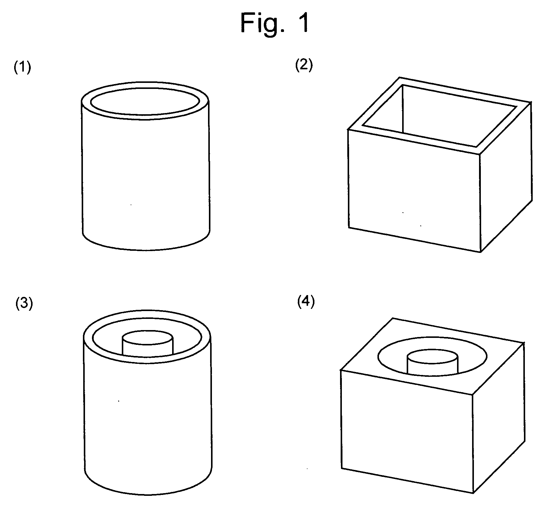
[0235] Preferably, the mold should be made of a material that can withstand the high sintering temperature (up to 1100 degrees Celsius). In the course of pre-heating the mold, the particles loosely combine with each other, whereby the object to be sintered becomes able to sustain its shape. In this preliminary sintered state, a portion or the entirety of the mold can be removed so that the preliminary sintered body can be set into another mold or onto a bedplate. The preliminary sintering temperature is preferably from 500 degrees Celsius to a level that is 30 degrees Celsius lower than the sintering temperature. The mold used in the preliminary sintering process can be made of any material that withstands the above temperature range.

[0236] Examples of the mold material include iron, iron alloy, stainless steel, permalloy, heat resisting steel, heat resisting alloy and superalloy; molybdenum, tungsten and their alloy; and ferrite, alumina and other ceramics.

[0237] [Co...


PUM

PropertyMeasurementUnit
Grain sizeaaaaaaaaaa

Abstract

To improve the performance of a rare-earth magnet, it is effective to use a low-oxidized powder having a small grain size. One objective of the present invention is to provide a method for manufacturing a sintered rare-earth magnet having a magnetic anisotropy, in which a very active powder having a small grain size can be safely used in a low-oxidized state. Another objective is to provide a method capable of efficiently manufacturing products having various shapes. In a weighing and loading section 41 and a high-density loading section 42, a fine powder as a material of the sintered rare-earth magnet having a magnetic anisotropy is loaded into a mold until its density reaches a predetermined level. Then, in a magnetic orientation section 43, the fine powder is oriented by a pulsed magnetic field. Subsequently, the fine powder is not compressed but immediately sintered in a sintering furnace 44. The present method enables the mass-producing machine to be simple in its operation and its housing to be accordingly smaller, so that it will be possible to eliminate the danger of oxidization or burning of the powder, which has been a serious problem for a conventional method that uses a large-scale die-pressing machine. Furthermore, the manufacturing efficiency can be improved by using a multi-cavity mold for manufacturing a sintered rare-earth magnet having an industrially important shape, such as a plate magnet or an arched plate magnet.

Description

TECHNICAL FIELD [0001] The present invention relates to a method for manufacturing a high-performance rare-earth magnet and a system for the method. BACKGROUND ART [0002] A sintered rare-earth / iron / boron magnet, which is called “RFeB magnet” hereinafter, was introduced in 1982 and is steadily spreading their fields of commercial application as ideal materials for permanent magnets. They can be produced at low costs from neodymium, iron, boron and other materials abundantly present in nature. Moreover, their characteristics are much better than those of their predecessors. The major application areas of the RFeB magnets are: voice coil motors (VCMs) for actuating magnetic heads of hard disk drives (HDDs) used in computers; high-quality speakers; headphones; battery-assisted bicycles; golf carts; and magnetic resonance imaging (MRI) apparatuses using permanent magnets. They are also coming into practical use in drive motors for hybrid cars. [0003] The RFeB magnet was discovered by the...

Claims


Application Information

Patent Timeline
IPC IPC(8): B22F3/10B22F7/00
CPCB22F3/1021B22F2998/10C22C1/0433C22C33/0278C22C38/005C22C38/06H01F41/0246C22C38/16H01F1/0557H01F1/0577H01F41/0273C22C38/10B22F2201/10B22F9/08B22F3/004B22F2202/01B22F3/005B22F2202/05B22F9/04H01F1/053
Inventor SAGAWA, MASATONAGATA, HIROSHIITATANI, OSAMU
Owner DAIDO STEEL CO LTD
Learn More