

Raman amplifier, optical repeater, and raman amplification method
- Summary
- Abstract
- Description
- Claims
- Application Information
AI Technical Summary
Benefits of technology
Problems solved by technology
Method used
Image

Examples
fourth embodiment
of Optical Repeater
[0140]FIG. 10 shows an example that, in the embodiment shown in FIG. 9, a control means for adjusting the gain of the Raman amplifier 9 by monitoring the light level is also provided between the first EDFA 10 and the Raman amplifier 9. By using such control means, the pumping light can be controlled to keep the difference between the input and output levels of the Raman amplifier 9 constant, with the result that only the dispersion of the loss of the DCF can be compensated.
fifth embodiment
of Optical Repeater
[0141]FIG. 11 shows an example that, in the above-mentioned embodiment, the gain flattening monitor mechanism is shifted to the output end of the repeater and is used as a monitor for flattening the gain of the entire repeater. In this case, the first EDFA 10 and the second EDFA 10 may perform the gain constant control or the output constant control. The powers of the pumping lights are independently controlled to reduce the level deviation between the output signals at the output of the repeater.
Sixth Embodiment of Optical Repeater
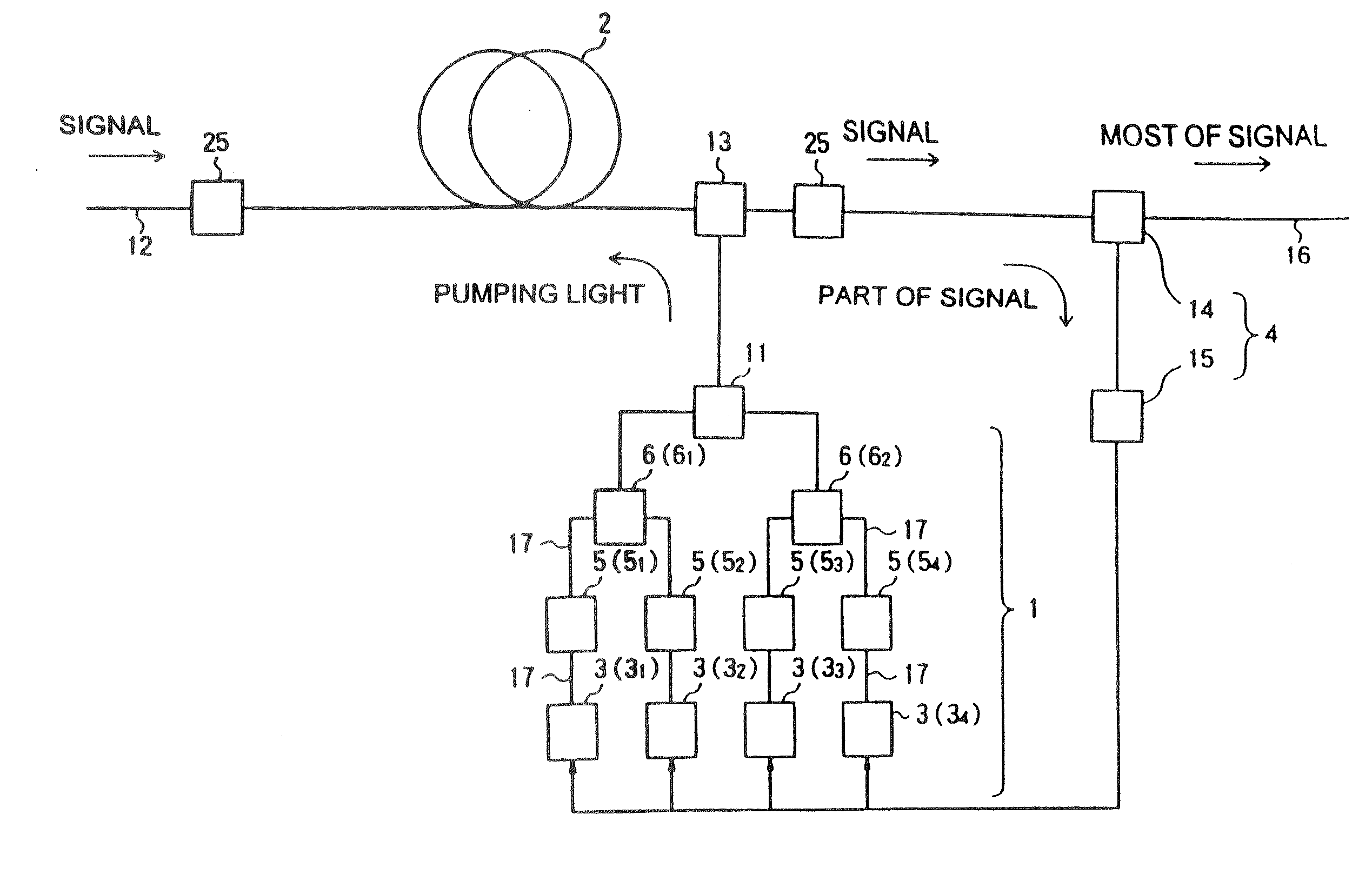
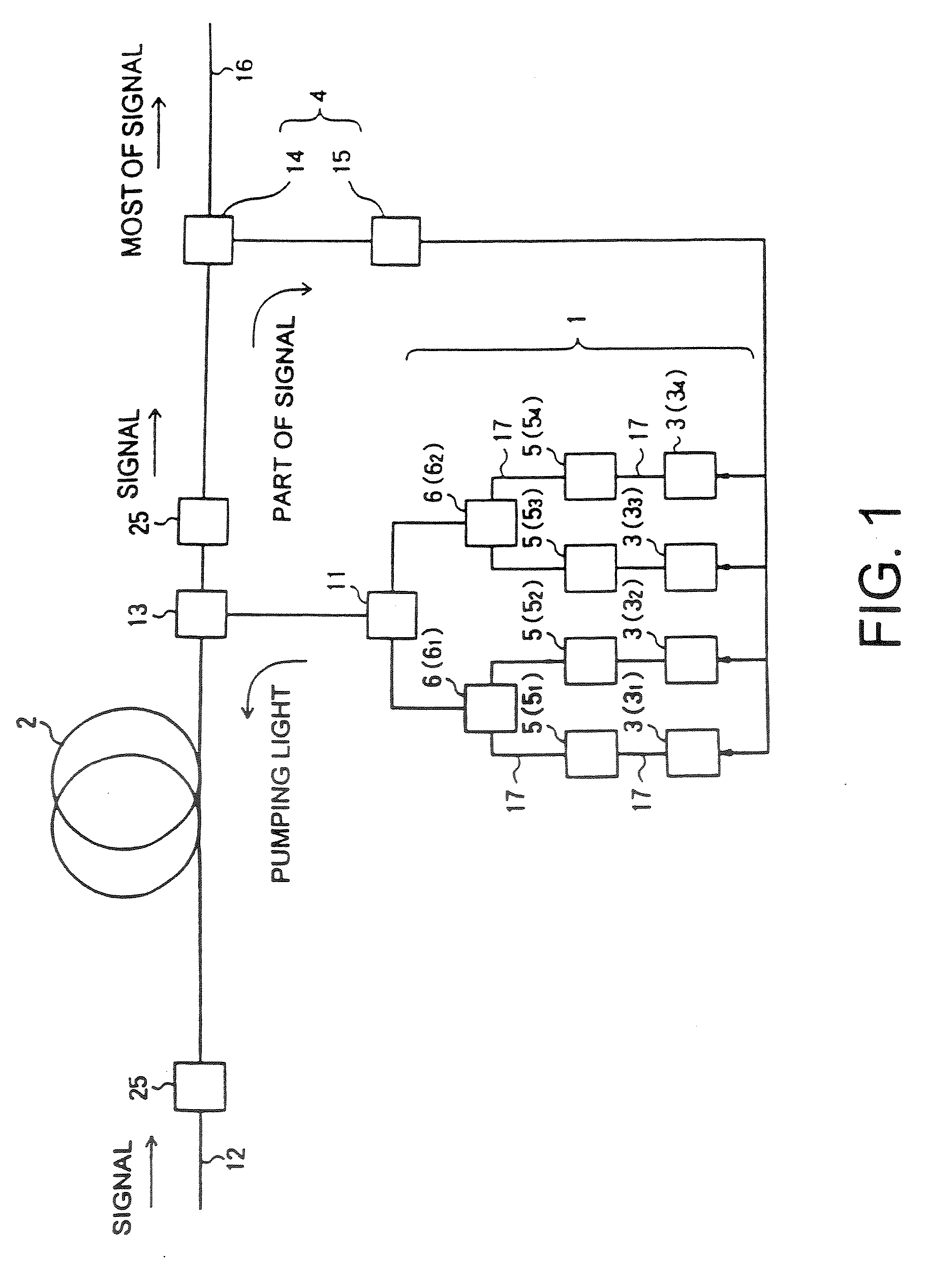
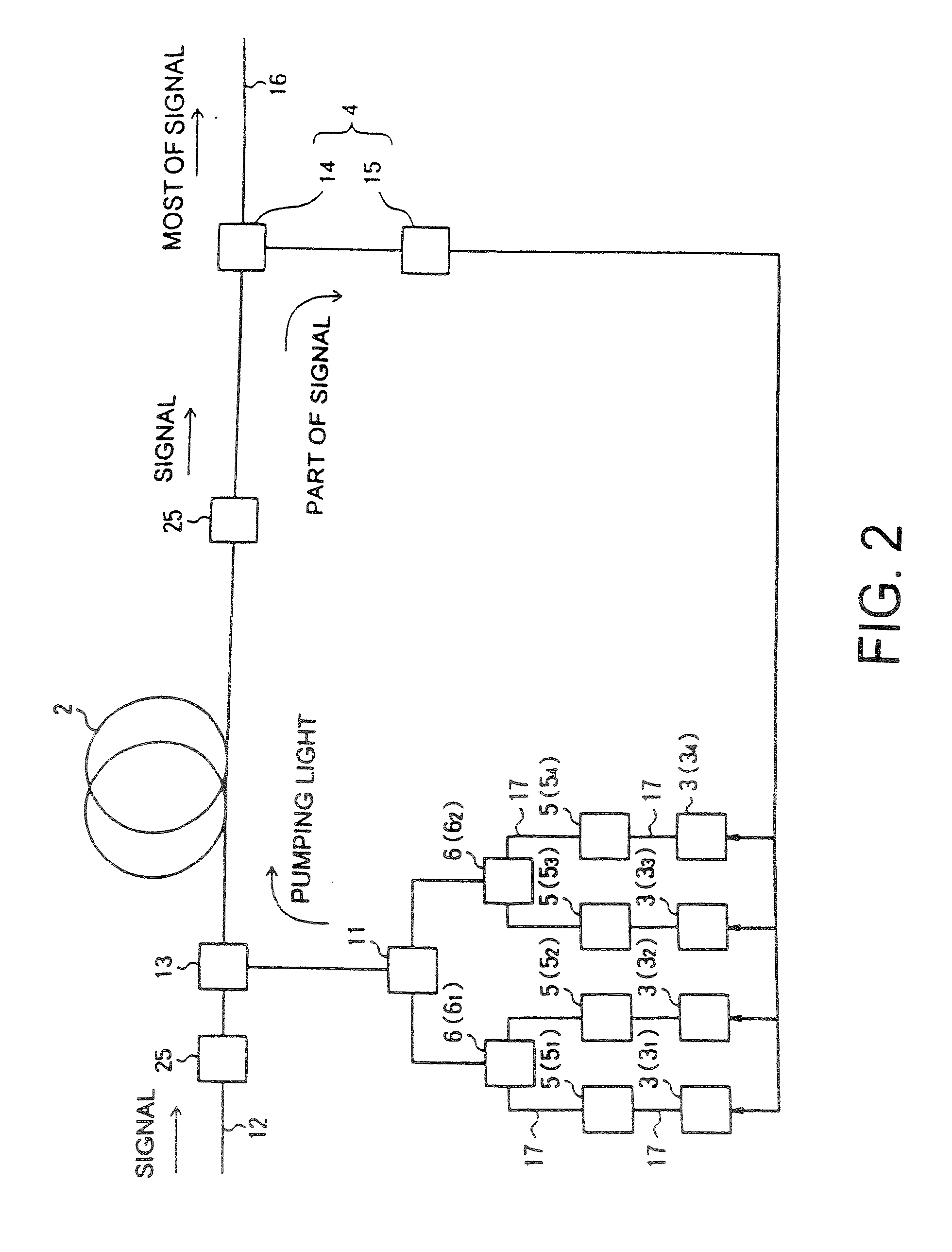
[0142] In an optical repeater according to a sixth embodiment of the present invention, a dispersion compensating fiber is used as the amplifier fiber 2 of the Raman amplifier shown in FIG. 1, 2 or 3 to compensate dispersion of wavelength of the optical fiber transmission line 8, so that the losses in the optical fiber transmission line 8 and the amplifier fiber 2 are compensated partially or totally.
Seventh Embodiment of Optical Rep...
first embodiment
of Raman Amplifying Method
[0146] An embodiment of a Raman amplifying method according to the present invention will now be fully explained with reference to FIGS. 49 to 52. In this embodiment, a dispersion compensating fiber (DCF) having high non-linearity is used in a Raman amplifying medium 50 shown in FIG. 49 and pumping light generated from an pumping light source 51 is inputted and transmitted to the Raman amplifying medium through a wave combiner 52. In this case, as shown in FIG. 50, as the pumping light source 50, a 4ch-WDMLD unit comprising four pumping light sources (semiconductor lasers), fiber Bragg gratings (FBG), polarization beam combiner (PBC) and a WDM is used. The semiconductor lasers shown in FIG. 50 generate pumping lights having different central wavelengths (more specifically, generate pumping lights having central wavelengths of 1435 nm, 1450 nm, 1465 nm and 1480 nm, respectively). These pumping lights give Raman gain to an optical signal transmitted from the ...
PUM
 Abstract
Description
Claims
Application Information