Internally cooled coated fiber device

a coating fiber and cooling technology, applied in the direction of component separation, material testing goods, chemical methods analysis, etc., can solve the problems of many matrices not releasing sufficient analytes, and insufficient analytes transferred to the fiber to produce a detectable signal

Inactive Publication Date: 2007-10-25
PAWLISZYN JANUSZ
View PDF18 Cites 27 Cited by
  • Summary
  • Abstract
  • Description
  • Claims
  • Application Information

AI Technical Summary

Benefits of technology

[0005]Among the various aspects of the present invention are improved internally cooled solid phase microextraction devices that provide for temperature control and repeated use without failure, and provide for quantitative sampling of volatile and semi-volatile organic compounds.

Problems solved by technology

Sometimes, the SPME approach suffers from disadvantages in that many matrices do not release sufficient analytes.
Thus, the analytes transferred to the fiber are not sufficient to produce a detectable signal when the analytes are desorbed in an analytical instrument.
Also, the SPME is typically not a quantitative extraction method and therefore, it requires careful calibration procedures.
Although useful, the sampling device design results in frequent septum replacement, frequent sorbent coating failure, sampler leakage, coolant supply tubing crimping and failure and the device was not readily adaptable for automation.

Method used


Image

  • Internally cooled coated fiber device
  • Internally cooled coated fiber device
  • Internally cooled coated fiber device

Examples


examples

[0060]The following non-limiting examples are provided to further illustrate the present invention.

examples 1-6

[0061]Toluene, ethyl benzene and o-xylene were purchased from Sigma-Aldrich (Mississauga, ON, Canada). HPLC grade methanol was purchased from BDH (Toronto, ON, Canada), and naphthalene, acenaphthene, and fluorene were purchased from Supelco (Oakville, ON, Canada).

[0062]Benzyl acetate, geraniol (3,7-dimethyl-2,6-octadien-1-ol), Cetalox® ((+−)-8,12-epoxy-13,14,15,16-tetranorlabdane), aroma model components (Hexanal, butyl acetate, (E)-2-hexenal, isoamyl acetate, isobutyl isobutyrate, hexyl acetate and heptyl acetate), and ethanol were from Firmenich (Geneva, Switzerland). Galaxolide® (1,3,4,6,7,8-hexahydro-4,6,6,7,8,8-hexamethyl-cyclopenta[G]isochromene) was purchased from IFF (New York, N.Y., USA). Unperfumed shampoo bases and perfumed shampoo samples were from Firmenich, including sodium lauryl sulfate based conditioning shampoo, ammonium lauryl sulfate based conditioning shampoo, sodium lauryl sulfate based simple shampoo and a sodium lauryl sulfate based benchmark conditioning sha...

example 1

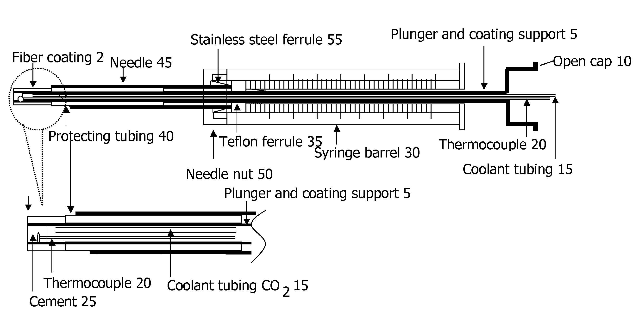
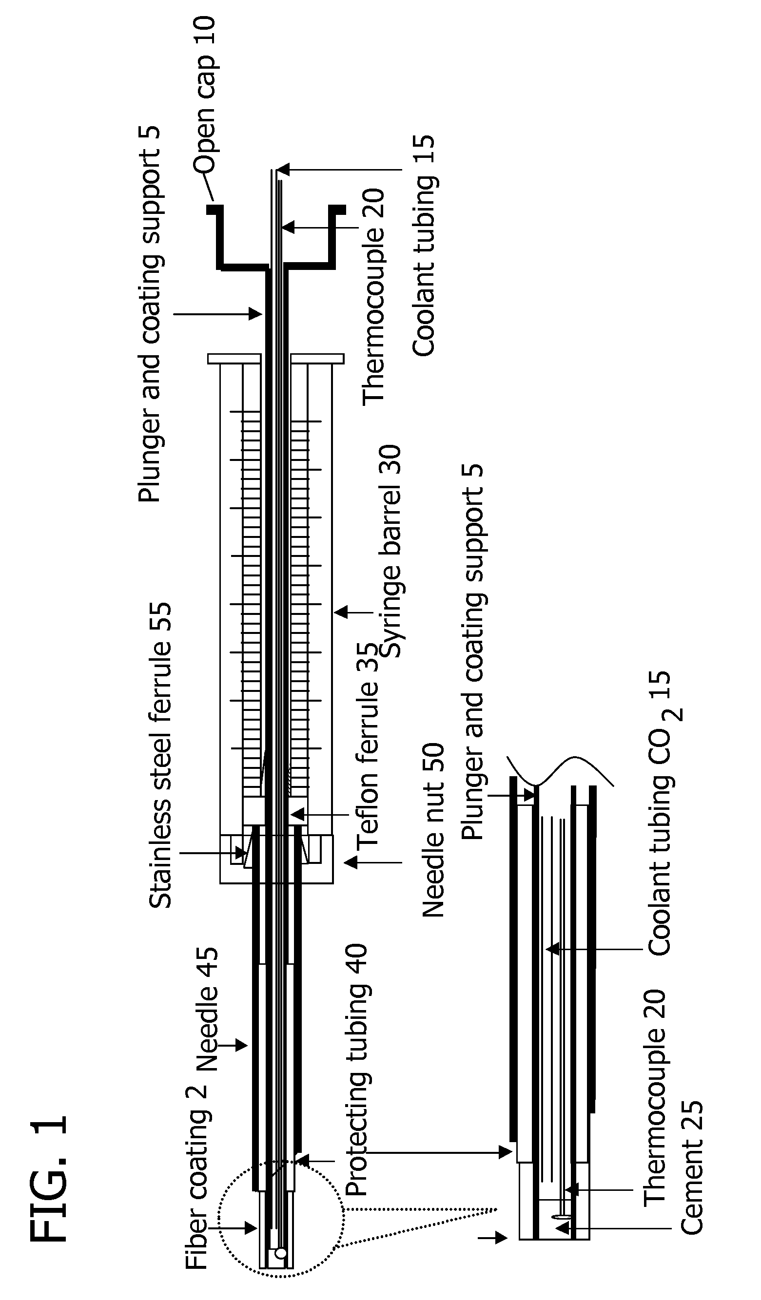
[0066]An internally cooled SPME device was fabricated. In reference to FIG. 1, a piece of 163-mm 22xx-gauge stainless steel tubing was used as plunger and fiber coating support 5. One end of the tubing 5 was connected to an open cap 10 by silver meld. The open cap 10 was used to provide a physical connection with an autosampler (not shown) so that the fiber coating 2 could be exposed outside the needle 45 or automatically withdrawn inside the needle 45 via an autosampler injection arm (not shown). The cap 10 had a large inner volume that provided sufficient space to bend the CO2 delivering tubing 15 to 90 degrees when the cap 10 was mounted in the autosampler injection arm (not shown). The other end of the tubing 5 was sealed with high temperature cement 25. The thermocouple 20 used to monitor the temperature of the fiber coating 2 was pulled through the plunger 5 from the open cap 10 to the fiber coating 2 prior to the seal. The probe of the thermocouple 20 was located inside the p...


PUM

PropertyMeasurementUnit
internal diameteraaaaaaaaaa
external diameteraaaaaaaaaa

Abstract

An internally cooled solid phase microextraction device that provides for quantitative sampling of volatile and semi-volatile organic compounds in complex samples. The device temperature is controlled the device design enables repeated use without failure. The device is miniaturized allowing it to be used with autosamplers known in the art.

Description

FIELD OF THE INVENTION[0001]The present invention generally relates to an internally cooled coated fiber device and process for solid phase microextraction. The present invention increases analyte concentration in a fiber sorbent from a source of analytes contained in a sample by increasing the temperature differential between the sample and the fiber sorbent.BACKGROUND OF THE INVENTION[0002]As described in U.S. Pat. No. 6,537,827 (to Pawliszyn), it is known to extract analytes using a sorbent fiber (either uncoated or coated with a polymeric coating) to extract organic compounds from their matrix and to directly transfer the analytes to an analytical instrument through thermal desorption. For example, the analytes can be transferred into a gas chromatograph through thermal desorption in a GC injector. The fiber can extract the analytes by dipping all or part of the fiber directly into the sample containing analytes or by contacting the fiber with a headspace located above the liqui...

Claims


Application Information

Patent Timeline
Patent Type & Authority Applications(United States)
IPC IPC(8): B01L11/00B01L99/00
CPCB01J20/28014G01N1/405G01N2030/128G01N2030/009G01N2030/126G01N30/12G01N2030/062
Inventor PAWLISZYN, JANUSZCHEN, YONG
Owner PAWLISZYN JANUSZ
Why Eureka
Try Eureka