Echogenic coatings with overcoat

a technology of overcoat and echogenic coating, which is applied in the field of echogenic coating, can solve the problems of not enhancing the ultrasound visibility of insertable medical devices, not as good as the other technologies, and increasing medical care costs and patient discomfort, so as to increase the ultrasound scattering, enhance the ultrasound visibility of surfaces, and improve the effect of ultrasound scattering

Inactive Publication Date: 2007-11-01
ANGIOTECH BIOCOATINGS
View PDF73 Cites 29 Cited by
  • Summary
  • Abstract
  • Description
  • Claims
  • Application Information

AI Technical Summary

Benefits of technology

[0013] The invention succeeds at providing a broadly applicable method of enhancing the ultrasound visibility of surfaces, an objective which previous efforts have failed to reach. The invention solves two problems of the prior art—providing the medical device with an acoustic impedance quite different from that of the animal or human tissue into which it is placed (high acoustic impedance differential), and increasing ultrasound scattering—by a simple, inexpensive, reproducible means of applying a polymer composite coating that has acoustical irregularities. The coatings of the invention are easily made by a variety of methods. They do not require solid particles or particle preparations and do not require machining or extrusion, elements employed in the prior art. Nonetheless, the coatings of the invention provide improved echogenicity.
[0034] The gaseous spaces may be located within the echogenic layer or between the echogenic layer and a top layer or the target material. Preferably, the gaseous spaces must be compressible. If they are pores or channels with trapped gas exposed directly to the target material, they are suitably compressible. If the gaseous spaces are enclosed within the polymer matrix or covered by a top coat, the material separating the gaseous space from the target material must be thin enough and flexible enough that the gas remains compressible. A gaseous space separated from the material to be visualized by a hard or thick film is not likely to contribute much echogenicity. Preferably, the flexibility of any covering over the gaseous space is such that it does not significantly reduce the compressibility of the underlaying gas, for example by no more than one order of magnitude. This effect is best achieved if there is no more than several microns of coating material over the gaseous space, such as less than about 5 microns, preferably between about 1 and about 2 microns.

Problems solved by technology

However, currently the contrast resolution of ultrasound is not as good as the other technologies.
Such contrast agents may enhance the visibility of target tissue into which they are injected, but they can not enhance the ultrasound visibility of insertable medical devices.
Inaccurate device placement may create a need to repeat a procedure thereby adding to medical care costs and patient discomfort or may, in some cases, result in a false negative diagnosis for example if a biopsy needle missed a lesion.
Worse, misplacement may harm a patient directly.
Consequently visibility of the device is poor and accurate placement becomes extremely difficult if not impossible.
Another problem affecting the visibility of devices is the scattering angle.
This approach improves the angle of echo scattering, but the intensity of the scattered signal is less than ideal, and at any angle other than the optimum, signals are lost into the background speckle.
One problem with this approach is that the interface layer is generated during the extrusion process for forming a plastic device, or by soldering, or ion beam deposition, which are inapplicable to many devices, and are expensive and difficult to control.
Also the differences in acoustical properties between glass or metal and body cavities are not very large, so echogenicity is not greatly enhanced.
Further, the described devices are not smooth since the echogenicity is produced either by indentations in the surface or the addition of metal or glass balls of diameter greater than the thickness of the interface layer.
The presence of the particles complicates the manufacturing process, and may weaken the surface of the device which can lead to sloughing of particles, device failure, or instability of the desired effect.
Such coatings have not found their way into the market.

Method used


Image

  • Echogenic coatings with overcoat
  • Echogenic coatings with overcoat
  • Echogenic coatings with overcoat

Examples


example 1

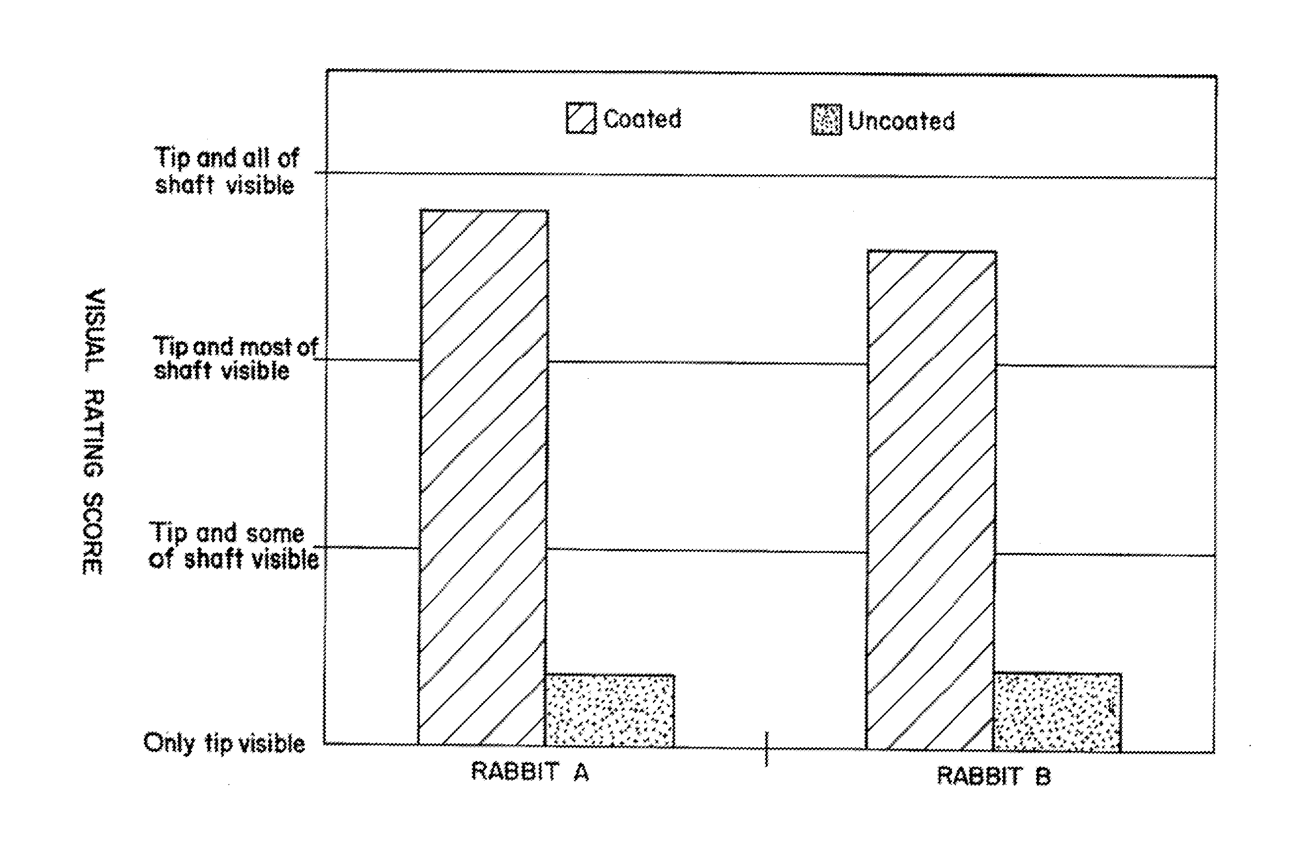
[0117] A steel wire was dip-coated in a precoat solution consisting of an acrylic polymer, a polyolefin / acrylic co-polymer, and isocyanate, dissolved in a mixture of tetrahydrofuran and cyclohexanone, and cured. The wire was then dip-coated in a base coat solution consisting of cellulose ester, an acrylic polymer, and a polyurethane resin, dissolved in a mixture of solvents including cyclohexanone, tetrahydrofuran, ethyl acetate, and benzyl alcohol, and cured. This device was then coated with an echogenic coating solution comprising 20% isocyanate pre-polymer dissolved in a mixture of 50 percent (w / w) dimethylsulfoxide in tetrahydrofuran. The coating was then partially dried at room temperature for 3 to 5 minutes to allow some of the THF (which is the more volatile solvent) to evaporate. The isocyanate pre-polymer polymerizes on exposure to water and gives off carbon dioxide. The device was dipped in water at room temperature for three minutes to cause the polymerization reaction to...

example 2

[0118] A steel wire was coated with a precoat and basecoat as in Example 1. The wire was then coated with a 20% isocyanate prepolymer dissolved in tetrahydrofuran with 1% surfactant (silicone). Polymerization was brought about by applying steam to the coated device for two minutes. An echogenic coating of the bubble / cavity / pore type was formed.

example 3

[0119] An echogenic coating solution contained 90% acrylic polymer in water. This liquid was sonicated for 40 seconds to provide the desired bubble size. A wire was coated with the coating liquid and dried in air at room temperature. An echogenic coating with channels was formed.


PUM

PropertyMeasurementUnit
thicknessaaaaaaaaaa
thicknessaaaaaaaaaa
flexural modulusaaaaaaaaaa

Abstract

An ultrasonically visible solid device for inserting into a non-gas target medium comprises an echogenic surface having structures entrapping gas when the device is in the target medium, the entrapped gas causing the device to be ultrasonically visible, wherein the gas-entrapping structures are covered with a flexible overcoat that does not significantly reduce the compressibility of the gas trapped in the structures.

Description

[0001] This application is a continuation in part of U.S. patent application Ser. No. 09 / 366,193, filed Aug. 4, 1999, issuing as U.S. Pat. No. 6,661,016, which is a continuation of U.S. patent application Ser. No. 08 / 965,393, filed Nov. 11, 1997, issued as U.S. Pat. No. 6,106,473, claiming benefit of U.S. provisional patent application 60 / 034,045, filed Nov. 6, 1996, all of which are incorporated herein by reference in their entirety.BACKGROUND OF THE INVENTION [0002] 1. Field of the Invention [0003] This invention relates to echogenic coatings for biomedical devices, and methods of preparing them. The coatings include echogenic irregularities and dramatically improve the visibility of the devices when viewed using ultrasound imaging techniques. [0004] 2. Background Information [0005] Ultrasonic imaging has many applications. This technology is especially valuable for medical imaging applications because diagnostic ultrasound procedures are safe, very acceptable to patients and less...

Claims


Application Information

Patent Timeline
Patent Type & Authority Applications(United States)
IPC IPC(8): A61B8/00A61B17/00A61B19/00A61F2/82A61KA61K49/22
CPCA61B8/0841A61L29/18A61B19/54A61B2017/00526A61B2017/00831A61B2017/00853A61B2017/00893A61B2019/5425A61K49/222A61K49/226A61L27/34A61L29/085A61L31/10A61L31/18A61B8/481A61B90/39A61B2090/3925
Inventor VIOLANTE, MICHAEL R.WHITBOURNE, RICHARD J.LANZAFAME, JOHN F.LYDON, MARGARET
Owner ANGIOTECH BIOCOATINGS
Why Eureka
Try Eureka