
Dense fluid cleaning centrifugal phase shifting separation process and apparatus

a technology of centrifugal phase shifting and dense fluid, which is applied in the direction of cleaning using liquids, centrifuges, separation processes, etc., can solve the problems of recontamination of substrates, formation of dry ice, and no dense fluid centrifuge or centrifugal process is similar

Inactive Publication Date: 2007-11-08
HITACHI HIGH-TECH CORP
View PDF8 Cites 15 Cited by
  • Summary
  • Abstract
  • Description
  • Claims
  • Application Information

AI Technical Summary

Benefits of technology

[0018] The present invention selectively controls the phase change of carbon dioxide between a“solvent” phase (saturated liquid phase) and “non-solvent” phase (saturated vapor phase) at relatively constant pressure and temperature—isothermal and isobaric change. Precipitated contaminants are separated from a substrate contained in a turbulent “centrifugal zone” of the dense fluid centrifuge by centripetal force and “transported” by centripetal force to a non-turbulent and circumferential “separation zone” located at the walls of the dense fluid centrifuge. The present invention uses a process of controlled phase shifting no need to transfer contaminated fluid out of the cleaning vessel to prevent redeposition onto substrates.
[0020] A dense fluid centrifuge is also illustrated which can accommodate heavier and eccentric substrate loads, higher rotational velocities, different centrifuge drum designs, spray-under-immersion operations, and liquid-liquid extraction capability. It may also be oriented between the horizontal and vertical planes for improved process capability, system versatility and cleaning performance. Novel processes including centrifugal froth flotation and liquid-liquid extraction are also detailed used as in-situ adjuncts—enhancing additive mixing with carbon dioxide, extracting metallic fines / chips from deep dead-end holes of machined products, scouring particles from filaments of fabrics and performing cleaning of devices not possible using liquid carbon dioxide alone such as stripping plastic coatings from surfaces.
[0024] In an embodiment is the minimization of the explosive decompression of polymers through the centrifugal wringing action of the centrifuge in combination with a phase shift operation which exchanges liquid carbon dioxide with vapor having much lower molar volume (density) which in-turn reduces the risk of the explosion of the polymers during the expansion of liquid carbon dioxide allowed to remain in contact with the polymer.

Problems solved by technology

However, none utilize a dense fluid centrifuge or centrifugal processes similar to those detailed herein.
The use of conventional dense fluid cleaning technology may result in a pooling and supercooling of liquid carbon dioxide trapped within pores and cavities of a substrate—leading to the formation of dry ice and recontamination of substrate.

Method used


Image

  • Dense fluid cleaning centrifugal phase shifting separation process and apparatus
  • Dense fluid cleaning centrifugal phase shifting separation process and apparatus
  • Dense fluid cleaning centrifugal phase shifting separation process and apparatus

Examples


Embodiment Construction

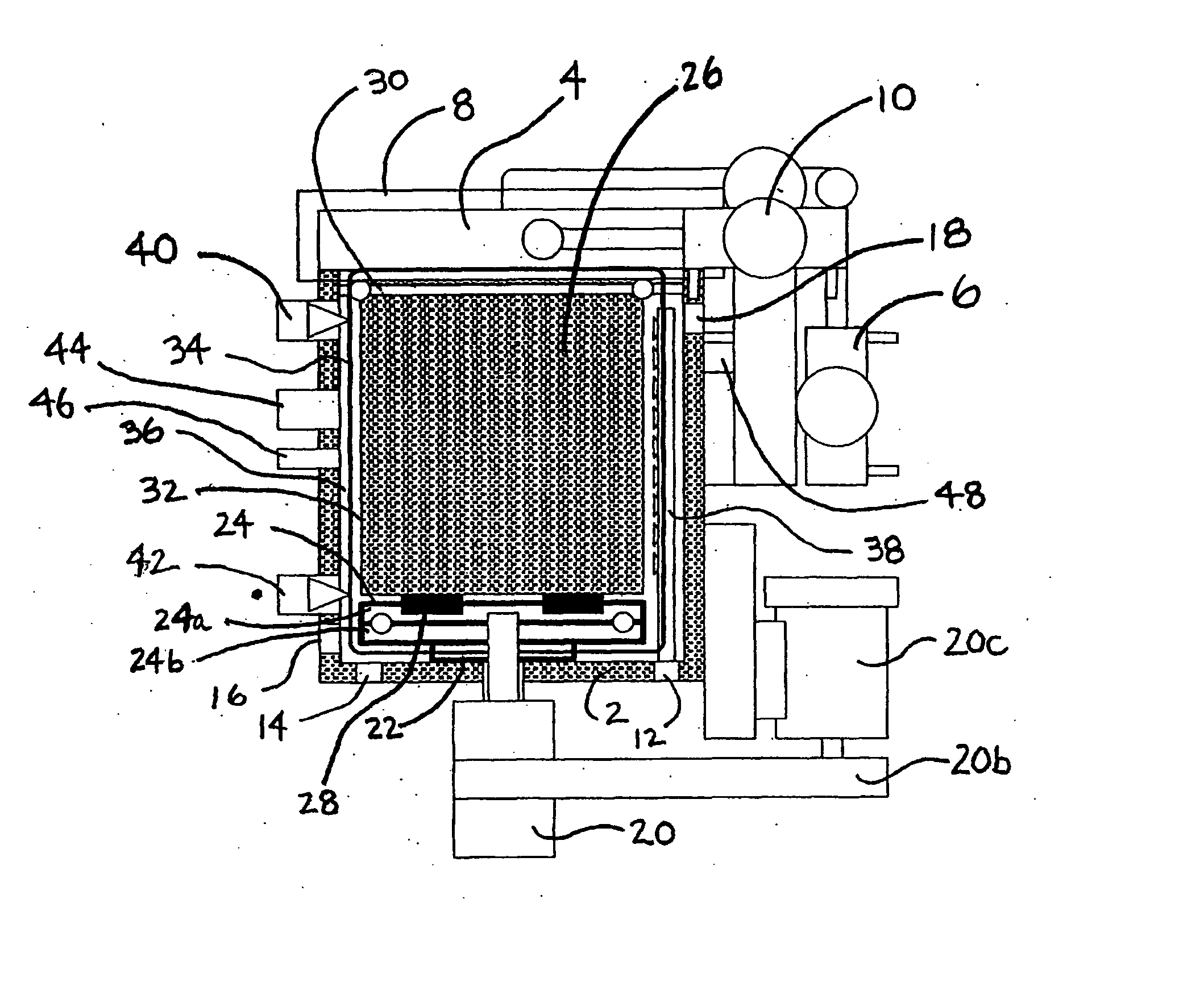
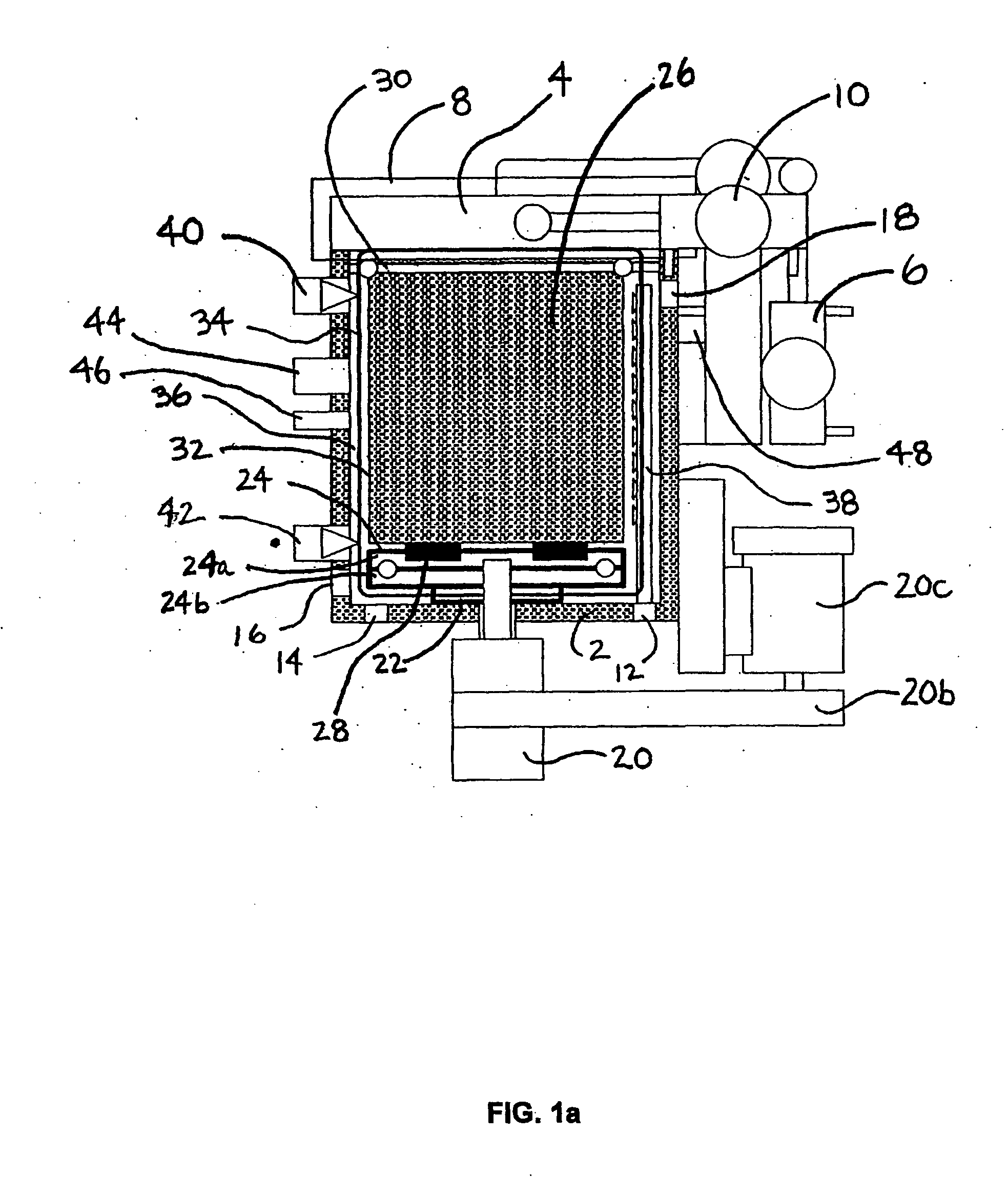
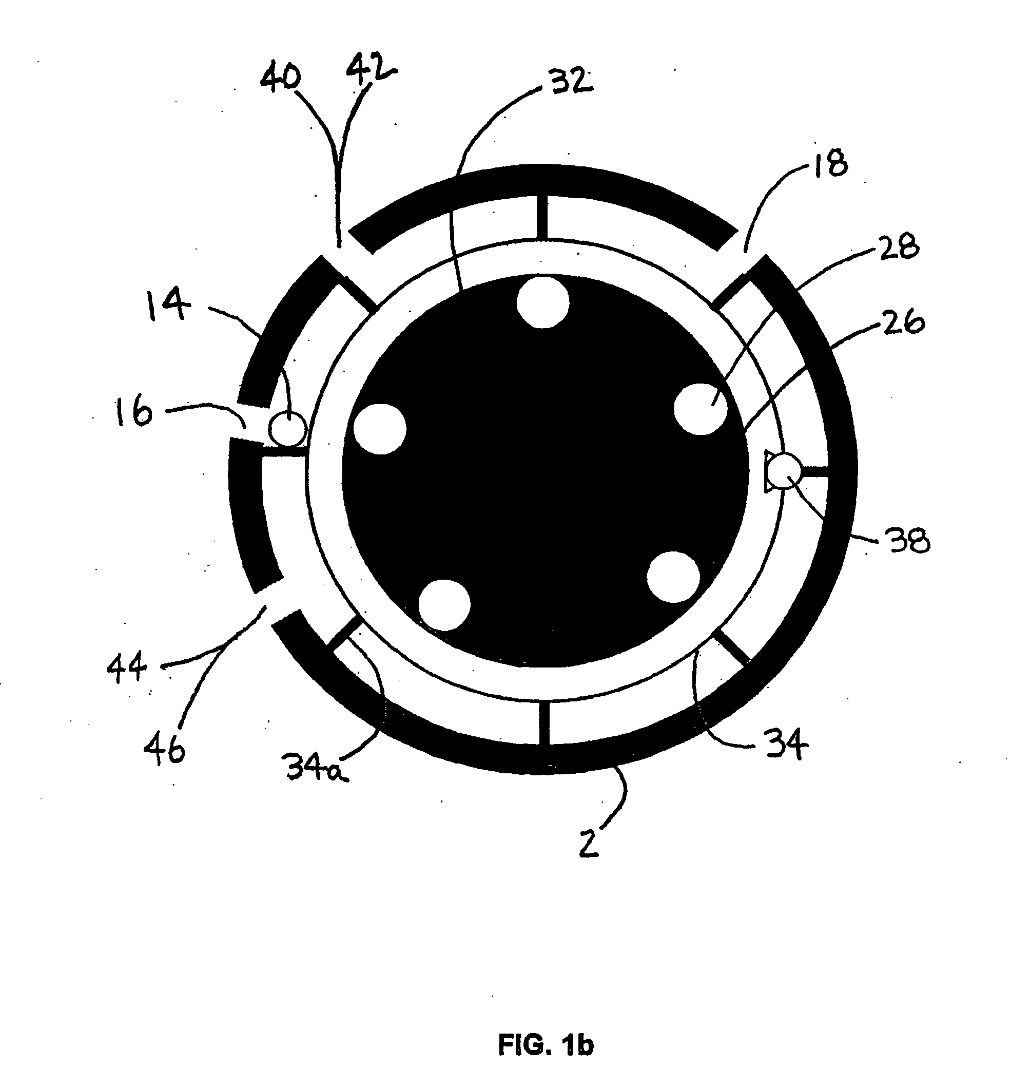
[0052] Shown in FIG. 1a is a side view of the dense fluid centrifuge used to perform the various processes of the present invention generally designated (1). The dense fluid centrifuge (1) has a high pressure vessel (2) with high pressure centrifuge lid (4) which is operated using a hydraulic lift cylinder (6). The centrifuge lid (4), when closed as shown, is secured to and seals the high pressure vessel (2) using a rotating locking ring (8) which is rotated using a hydraulic ring closure cylinder (10). The high pressure vessel (2) contains several ports for filling and draining the dense fluid centrifuge under isobaric and isothermic conditions. A fill port (12) is located in the lower half of the pressure vessel (2). A first drain port (14) used during draining in the vertical orientation of the dense fluid centrifuge is located in the lower half of the pressure vessel (2). A second drain port (16) used during draining in the horizontal orientation is located in the lower half of ...


PUM

PropertyMeasurementUnit
Pressureaaaaaaaaaa
Speedaaaaaaaaaa
Phaseaaaaaaaaaa

Abstract

The present invention is an apparatus and process for cleaning substrates using fluids, including dense fluids. A perforated centrifuge drum operates within a pressure vessel. A dense fluid cleaning and management system including suitable process condition sensors provides for exchanging fluid with the pressure vessel.

Description

[0001] This application is a Continuation in part of Ser. No. 10 / 897,672 filed Jul. 23, 2004, which is a Continuation of Ser. No. 10 / 221,767 filed Sep. 12, 2002 now U.S. Pat. No. 6,802,961, which is a 371 of PCT / US01 / 08054 filed Mar. 13, 2001 and claiming priority to U.S. provisional application 60 / 189,079, filed Mar. 13, 2000.BACKGROUND OF INVENTION [0002] 1. Field of Invention [0003] The present invention relates to dense fluid cleaning. More particularly to the use of a dense fluid such as carbon dioxide in a process of centrifugal phase shifting separation as an environmentally sound alternative to organic solvents. [0004] 2. Description of Related Art [0005] Liquid-phase phase carbon dioxide cleaning devices and processes can be found in the art. However, none utilize a dense fluid centrifuge or centrifugal processes similar to those detailed herein. [0006] Carbon dioxide exists as a low-density gas at standard temperature and pressure conditions and possesses phase boundaries ...

Claims


Application Information

Patent Timeline
IPC IPC(8): B04B5/10B04B9/00
CPCB01D2011/007B08B3/06B01D11/0407B08B7/0021B01D11/0403B01D11/0476
Inventor JACKSON, DAVID P.
Owner HITACHI HIGH-TECH CORP
Learn More