
Combined gasification and vitrification system

Active Publication Date: 2007-11-15
INENTEC
View PDF13 Cites 38 Cited by
  • Summary
  • Abstract
  • Description
  • Claims
  • Application Information

AI Technical Summary

Benefits of technology

[0013] Accordingly, the present invention is an improved method for processing organic and heterogeneous feedstocks. It is an object of the present invention to provide a system that is capable of treating mixtures of inorganic materials, biomass, and fossil-based organic materials and their derivatives, including waste derived from the production and use of such fossil-based organic materials, and to convert them into a clean fuel gas and an environmentally stable glass. It is a further object of the present invention to provide a method and apparatus for processing organic and / or heterogeneous feed stocks by providing a gasification unit which converts all or a portion of the organic components of waste to a hydrogen rich gas and ash, in communication with a joule heated vitrification unit which converts inorganic materials and ash formed in the gasification unit into glass, and a plasma which converts carbon and products of incomplete gasification formed in the gasification unit into a hydrogen rich gas. The resultant glass may be used as a useful product, such as a construction material, road aggregate or the like. Most importantly, the present invention does so in a manner that overcomes the tradeoffs associated with traditional gasification systems, and provides these benefits in a compact system that minimizes both the capital cost and the energy required to run the system.
[0018] The plenum space within the joule heated vitrification unit may be maintained as a reducing environment by eliminating or preventing the ingress of any additional ambient air or oxygen and maintaining an overpressure of an inert gas such as nitrogen. Alternatively, further partial oxidation may occur in the plenum space of the joule heated vitrification unit through the introduction of additional oxygen. Whether operated in a reducing environment or in a partial oxidation mode, steam or carbon dioxide may be added to the joule heated vitrification unit as a further oxidant.
[0026] For example, and not meant to be limiting, it is typical that complete oxidation in the gasification unit will generate a gaseous effluent with high levels of undesirable constituents, such as tars. The feedback control device would be configured to recognize that complete combustion was occurring in the gasification unit by measuring a combination of the parameters used to operate the gasification unit. For example, and not meant to be limiting, by measuring effluent gasses, the flow rates of the feedstock, and the flow rates of the oxidant the feedback control device could determine that complete combustion was occurring in the gasification unit. Having recognized an undesirable operation, the feedback control device could then increase the feed rates for one or both of the oxidant or the feedstock, thereby preventing complete combustion in the gasification unit.

Problems solved by technology

Since millions of years are required to form fossil fuels in the earth, their reserves are finite and subject to depletion as they are consumed.
While these and other gasification systems have shown a wide variety of benefits, several drawbacks are still present in their operation.
For example, these types of systems typically are not well suited to processing heterogeneous feed stocks, which are defined herein as feed stocks containing mixtures of organic and inorganic materials.
In many cases, the inorganic constituents of the feed stocks can adversely effect the processing of the organic portion, resulting in less than complete conversion, or low processing rates.
Also, the inorganic constituents may be left in a highly concentrated ash form, rendering them highly soluble into the environment, particularly ground water, and therefore potentially environmentally hazardous and / or requiring expensive treatment to stabilize these constituents prior to final disposal.
Even when operated with homogeneous organic feedstocks, gasification systems typically have drawbacks.
Instead, various oils, tars and other undesired components are present in the gas.
This results in a waste product of partially oxidized organic material that must be disposed of, often at great cost.
For this reason, the volatilization of the organic feedstock with a first heating source, prior to steam reforming the resultant gas with a second heating source, as described in both the Antal system and the Galloway system, imposes a significant economic penalty on these systems.
In the Kaske system, a plasma is used to reform “gaseous hydrocarbons are reformed with gaseous oxidizing agents, such as steam or carbon dioxide.” The systems described by Kaske thus suffer from many of the drawbacks found in the Galloway systems, in particular, the limitations which arise due to the focus on steam reforming volatilized organic gasses, as opposed to solid or liquid feedstocks.
In particular, the energy required to effect a phase change to form the steam injected in these systems can increase the costs of operating these systems significantly.

Method used


Image

  • Combined gasification and vitrification system
  • Combined gasification and vitrification system

Examples


Embodiment Construction

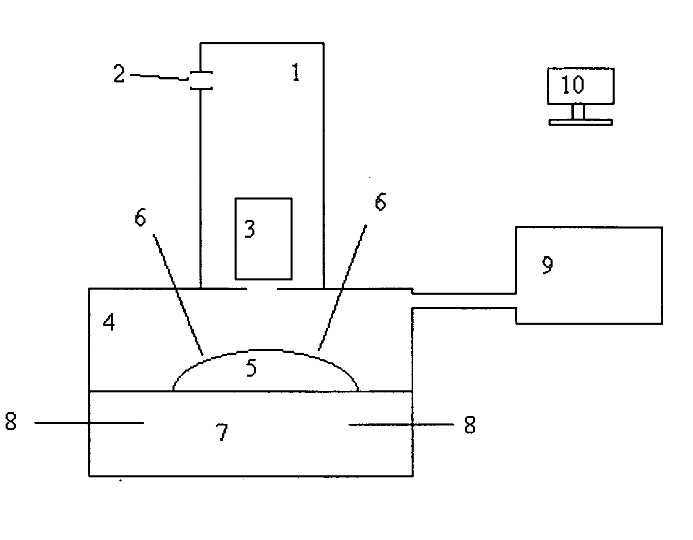
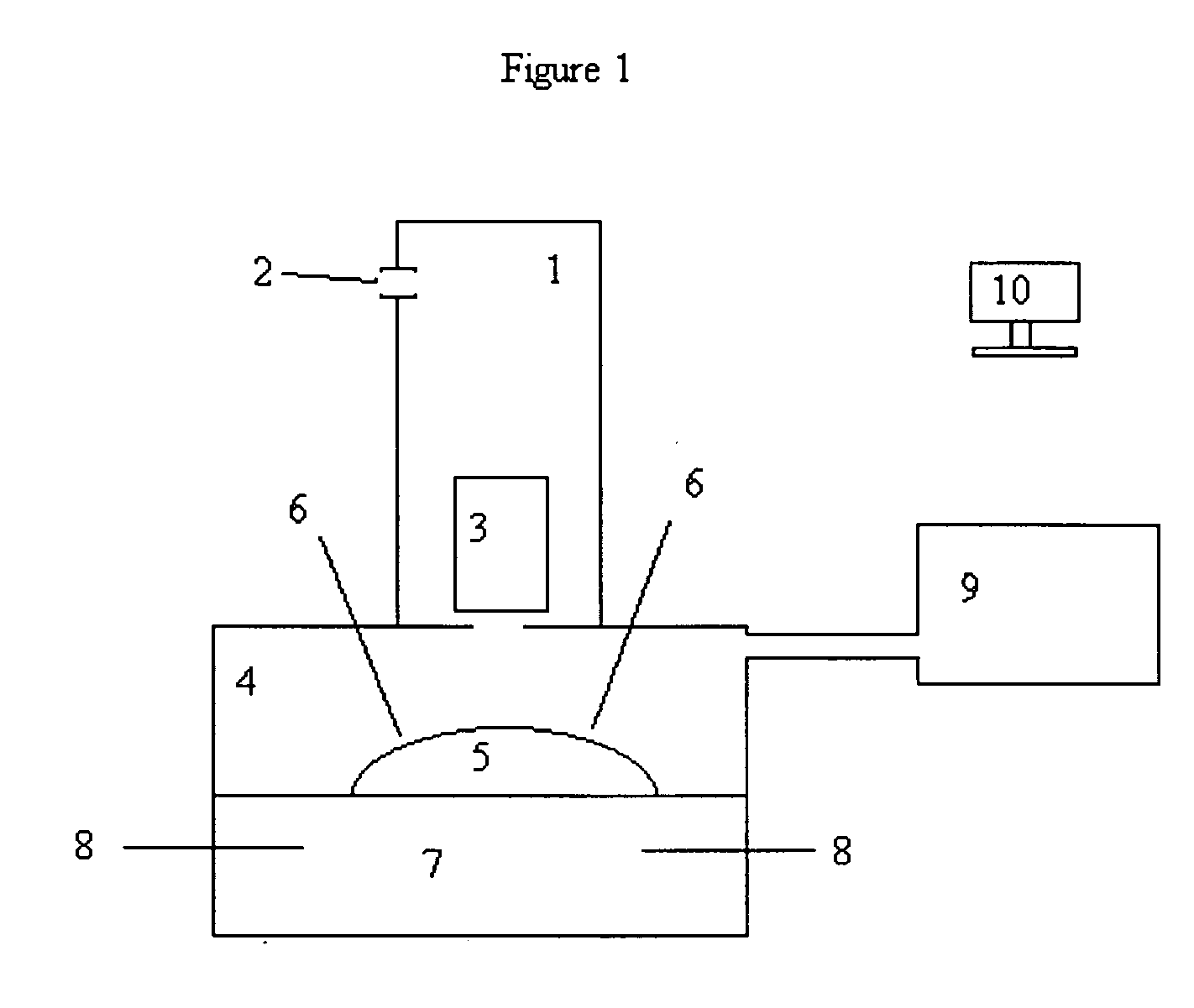
[0030] For the purposes of promoting an understanding of the principles of the invention, FIG. 1 provides a schematic illustration of the apparatus of the present invention configured with a downdraft gasification unit and an electrode plasma source. While this particular configuration is preferred, the present invention should in no way be limited to this configuration, and it should be understood that this configuration was selected merely for illustrative purposes.

[0031] As shown in the figure, organic materials are fed into a gasification unit 1. Oxidants, including but not limited to, oxygen, steam, carbon dioxide, air, oxygen enriched air, and combinations thereof, are fed into oxidant injection port 2. The gasification unit 1 is then operated as a normal, downdraft gassifier. A means for transporting organic material down the axial length of the downdraft gasifier is shown in the schematic as box 3. Any mechanical means suitable for moving solid material may be used, includi...


PUM

PropertyMeasurementUnit
Temperatureaaaaaaaaaa

Abstract

An optimized gasification / vitrification processing system having a gasification unit which converts organic materials to a hydrogen rich gas and ash in communication with a joule heated vitrification unit which converts the ash formed in the gasification unit into glass, and a plasma which converts elemental carbon and products of incomplete combustion formed in the gasification unit into a hydrogen rich gas.

Description

TECHNICAL FIELD [0001] The present invention relates generally to a method and apparatus for processing feedstocks containing organic materials. More specifically, the present invention relates to an integrated partial oxidation gasification and vitrification system which provides an improved method and apparatus for recovering the energy value from such feedstocks while rendering the inorganic portions in a safe and useable form. BACKGROUND OF THE INVENTION [0002] In the mid-1800s, biomass, principally woody biomass, supplied over 90% of U.S. energy and fuel needs. Thereafter, biomass energy usage began to decrease as fossil fuels became the preferred energy resources. Today, the world's energy markets rely heavily on fossil fuels, coal, petroleum crude oil, and natural gas as sources of energy. Since millions of years are required to form fossil fuels in the earth, their reserves are finite and subject to depletion as they are consumed. The only other naturally-occurring, energy-c...

Claims


Application Information

Patent Timeline
IPC IPC(8): C10J3/00
CPCB09B3/005C03B5/005C03B5/025C03B5/027C10J3/725C10J3/26C10J2300/16C10J3/723C10J2300/1634C10J3/08Y02P40/50B09B3/29C10J2300/0916C10J2300/1846
Inventor SURMA, JEFFREY E.BATDORF, JAMES A.
Owner INENTEC
Learn More