Detunable Rf Tags

a technology of rf tags and rf fuses, applied in the field of rf tags, can solve the problems of unreliable method of forming fuse fuse, many tags are either shorted during the manufacturing process or fail to blow, and achieve the effect of cheap manufacturing

Inactive Publication Date: 2007-11-22
QINETIQ LTD
View PDF10 Cites 17 Cited by
  • Summary
  • Abstract
  • Description
  • Claims
  • Application Information

AI Technical Summary

Benefits of technology

[0010] There is therefore a requirement for an alternative design of deactivator which can be activated by RF means and can be manufactured cheaply and reliably.

Problems solved by technology

To de-activate the tag it is subjected to a very high field at the resonant frequency which results in a high current causing breakdown of the dielectric substrate at this weak point thus shorting out the capacitor and eliminating the resonant response of the circuit.
This method of forming the fuse is known to be unreliable, presumably due to poor reproducibility of the weakening step.
Hence many tags are either shorted during the manufacturing process or fail to blow at the point of sale or re-activate some moments later after blowing.
This manifests as a poor resonant response which in turn influences the read range of the device at a given field strength or gate separation.
In some instances the fusible link may be prone to mechanical damage resulting in shorter read range or the gates blowing the fusible link.
If the fusible link becomes broken at any stage prior to de-activation it would render the device unreadable.
However such systems are inherently expensive to manufacture, often requiring memory elements in addition to the switch itself, and unsuited to low cost, high volume tags.

Method used


Image

  • Detunable Rf Tags
  • Detunable Rf Tags
  • Detunable Rf Tags

Examples


example 1

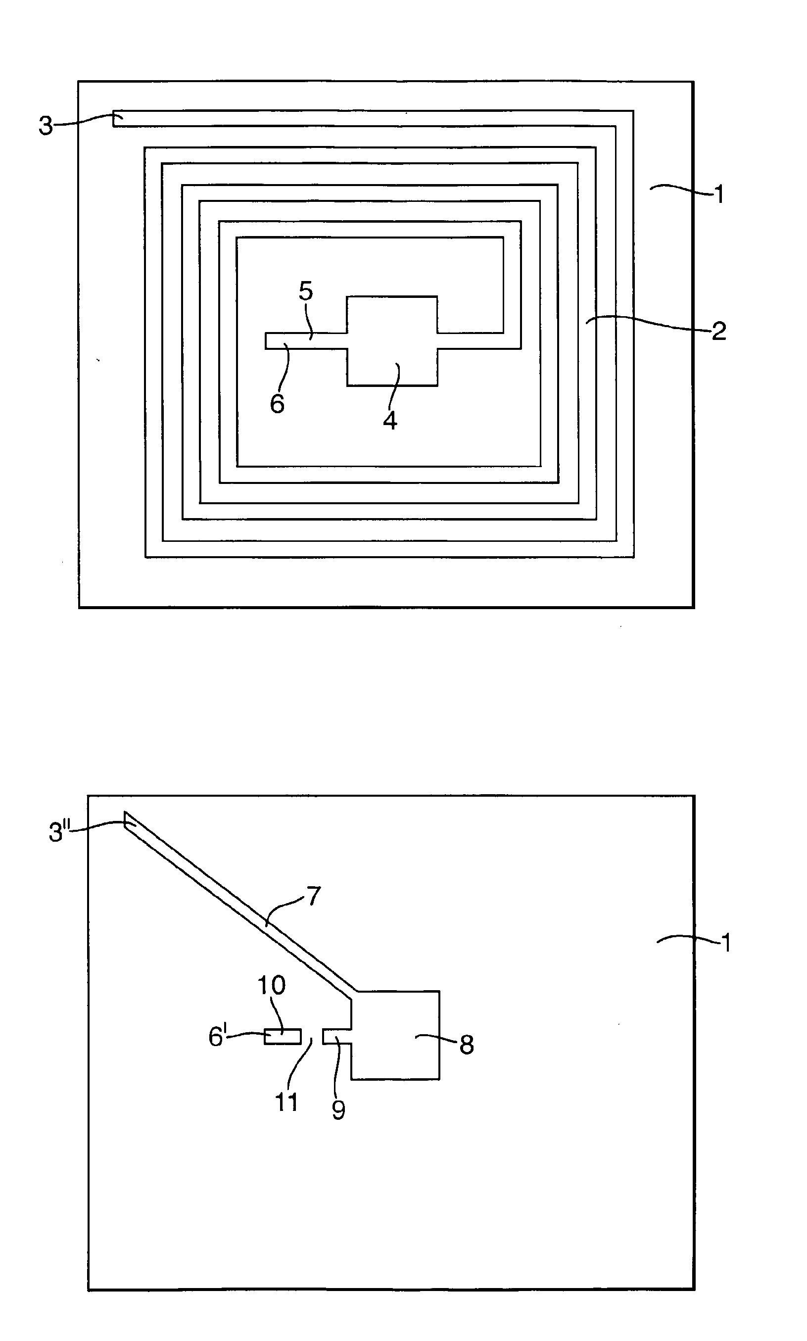
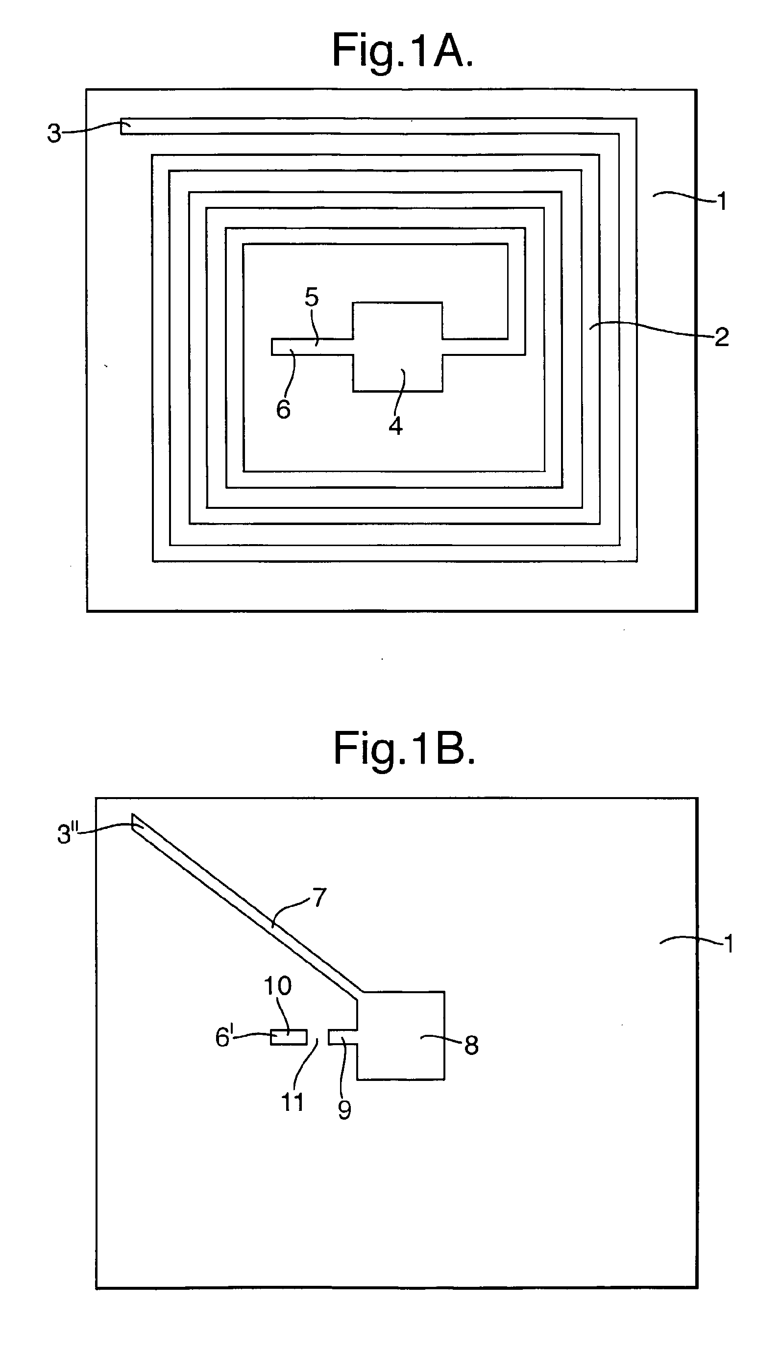
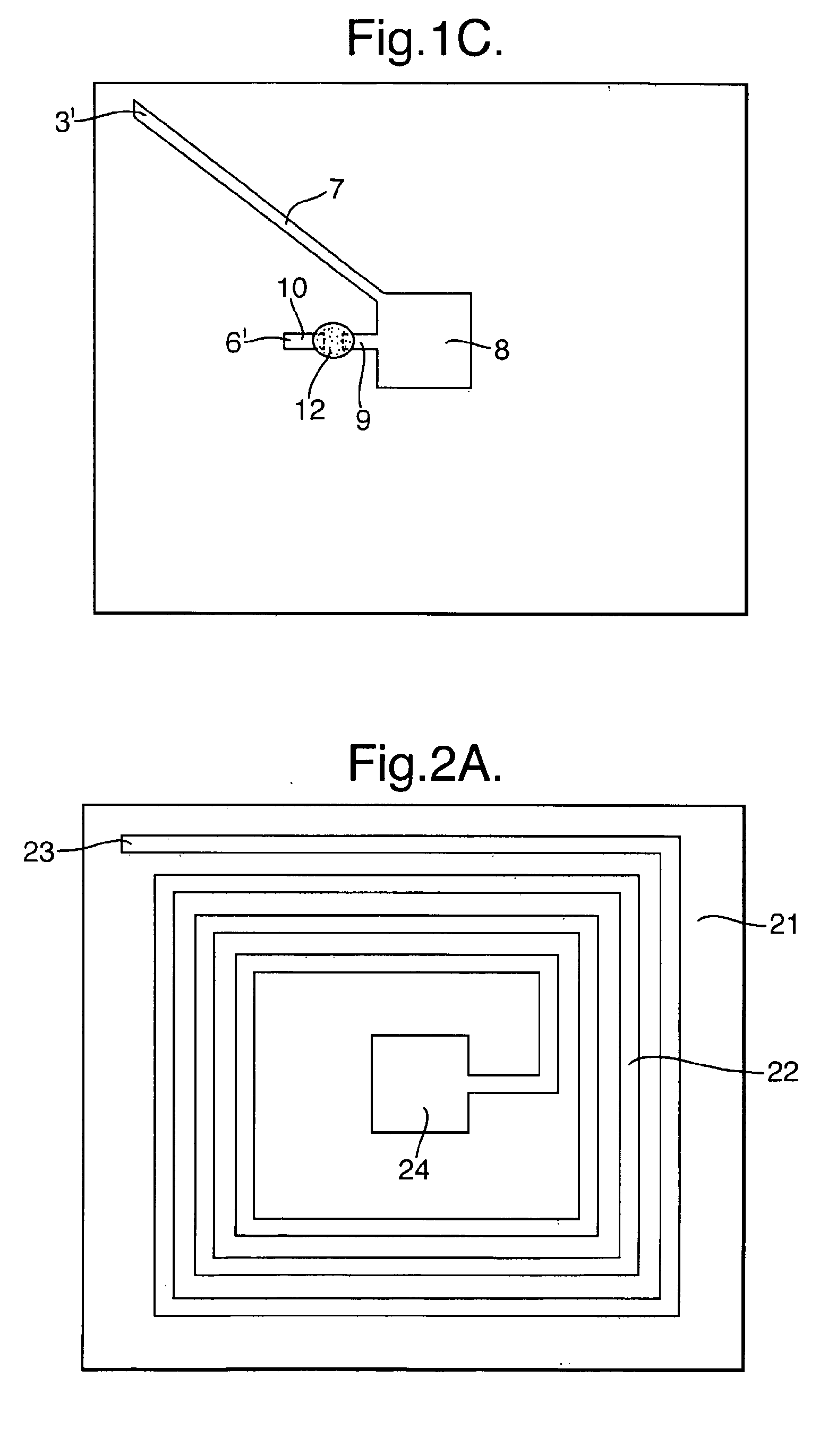
[0086] A tag was constructed in the form shown in FIGS. 1A to 1C. The metal tracks were of copper deposited by electroless plating and thickened by electroplating. The circuits on the two sides were connected by crimping at point 3 / 3′ and the contact hole 6 / 6′ was through-plated by the process used to print the metal tracks.

[0087] The switch composition 11 was formulated from an aqueous ink (Coates Aqualam screen print varnish) containing 30 weight percent of nickel flake having a sieve size −325 mesh (US standard mesh) and a mean particle size of 30 microns and 0.4 microns thick, supplied by Novamet. The switch composition was dropped onto the substrate and cured with UV light. The tag was connected to a Hewlett Packard 4192A LF impedance analyzer and tested for impedance response to an applied signal over the frequency range 7.5 to 9 MHz The resulting trace is shown at curve 41 in FIG. 3. This tag was found to trigger the alarm at a standard detector gate operating on a swept fre...

example 2

[0089] The tag was constructed as in Example 1. The switch composition 11 was formulated from a UV curing ink (Acheson PM025) containing 30 weight percent of the same nickel flake in example 1. The switch composition was dropped onto the substrate and cured with UV light. The testing was repeated and produced a similar trace to curve 41 in FIG. 3. This tag was found to trigger the alarm at the standard detector gate in Example 1. The tag was then passed over the tag blower used in Example 1. This resulted in a trace comparable to curve 42 in FIG. 3. The blown tag no longer triggered the alarm at a standard detector gate

example 3

[0090] The tag was constructed as in Example 1. The switch composition 11 was formulated from a solvent-containing ink (Polyplast PY made by Sericol) containing 10 weight percent of the same nickel flake in Example 1. The switch composition was dropped onto the substrate and cured with hot air drying. The testing was repeated and produced a similar trace to curve 41 in FIG. 3. This tag was found to trigger the alarm at the standard detector gate in Example 1. The tag was then passed over the tag blower used in Example 1. This resulted in a trace comparable to curve 42 in FIG. 3. The blown tag no longer triggered the alarm at a standard detector gate


PUM


Abstract

An RF tag suitable for use for electronic article surveillance comprises a tuned circuit formed by an inductive coil, which behaves as an antenna on a first side of a substrate electrically connected to a capacitor having plates on each side of an dielectric layer which may be the substrate. The capacitor and coil together form a resonant circuit. To permit deactivation of the tag the circuit also includes a discontinuity closed by a switch composition whose conducting properties can be changed from an insulating state to a conducting state when the tag is subjected to a strong electric field at or around its resonant frequency. The switch composition may, for example, be arranged to short out the capacitor plates or introduce additional capacitor plates or change the properties of the inductive coil. Alternatively the switch composition may introduce additional components (e.g. an IC) into the circuit. The tag may be arranged for sequential retuning to give a multifrequency tag. The switch composition may, for example, be an ink formulation containing 5 to 75% by weight a metal, preferably in the form of flakes. The switch composition may further contain oxygen scavengers or ionic species to improve the response of the switch composition and/or prevent the switch composition reverting to the insulating state.

Description

FIELD OF THE INVENTION [0001] The invention relates to radio-frequency (RF) tags which are capable of being detected by an external electric field and in particular to RF tags which can be activated, retuned / detuned and / or deactivated. Such tags are frequently used for Electronic Article Surveillance (EAS) to detect unauthorized articles being removed from enclosed areas such shops or libraries. [0002] Simple “one bit” EAS RF tags typically comprise a tuned circuit having inductive and capacitor components. A detector “gate” is arranged at the exit to the enclosed area and coils within the gate generate an electrical field at the resonant frequency of the tag. If the tag passes through the gate the field is disrupted and circuitry attached to the gate detects this disruption, which generates a signal which may in turn trigger an alarm. In practice the gate frequency commonly scans frequencies around the expected resonant frequency to allow for manufacturing variations in the tag. [0...

Claims


Application Information

Patent Timeline
Patent Type & Authority Applications(United States)
IPC IPC(8): G08B13/14H04Q5/22
CPCG08B13/242G08B13/2414
Inventor JOHNSON, DANIEL R.
Owner QINETIQ LTD
Why Eureka
Try Eureka