Information reproducing apparatus and method

Inactive Publication Date: 2007-11-29
HITACHI CONSUMER ELECTRONICS CORP
View PDF13 Cites 8 Cited by
  • Summary
  • Abstract
  • Description
  • Claims
  • Application Information

AI Technical Summary

Benefits of technology

[0054]The ROM disk was manufactured by the following steps. First, a recording pit of a concave-convex pattern for a CN ratio test having a mark and a space at constant intervals was formed on a photoresist by using a laser lithography system. The pit pattern was then photocopied to a Ni mold, and polycarbonate was injection-molded to the mold, thereby forming a substrate. The minimum pit size was set to 139 nm, and the depth of the pit was set to be 22 nm. The track pitch was set to be 320 nm.
[0055]A synthetic reflective film consisting of 95Ag-2.5Pd-2.5Cu (mol %) was formed on the manufactured substrate as the reflective layer 32. The film thickness was set to be 20 nm. The film was formed in pure Ar gas by DC magnetron sputtering. For protective films 33 and 35, amorphous films consisting of 80ZnS-20SiO2 (mol %) were used. The films were formed in pure Ar gas by an RF sputtering process. A thin film consisting of 50Fe2O3-50Ga2O3 (mol %) was used as the super-resolution layer 34. The film was formed in gas consisting of 95Ar-502 (flow percent) by RF sputtering. An oxide target having the same composition as the above was used as the sputtering target for forming this super-resolution layer.
[0056]After the films were formed by sputtering, the cover layer 36 was formed. UV curable resin was spin-coated on the substrate having a thickness of 1.1 mm, on which the thin films were formed, and then a polycarbonate cover layer having a thickness of 0.085 mm, which had been cut into a circular form having an external diameter of 119.5 mm and an internal diameter of 23 mm, was attached thereto. Next, the thus structured substrate was introduced into a vacuum chamber. The substrate and the sheet were caused to closely attach to each other by vacuum deaeration up to about 1 Pa. The UV curable resin was caused to be hardened by UV light irradiation from the side of the cover layer. The thickness of the UV resin was adjusted such that the total thickness of the UV curable resin and the cover layer would be 0.1 mm.
[0057]As for signals, a recording pit and a space that correspond to recording si

Problems solved by technology

Thus, it is difficult to obtain a

Method used


Image

  • Information reproducing apparatus and method
  • Information reproducing apparatus and method
  • Information reproducing apparatus and method

Examples


example 1

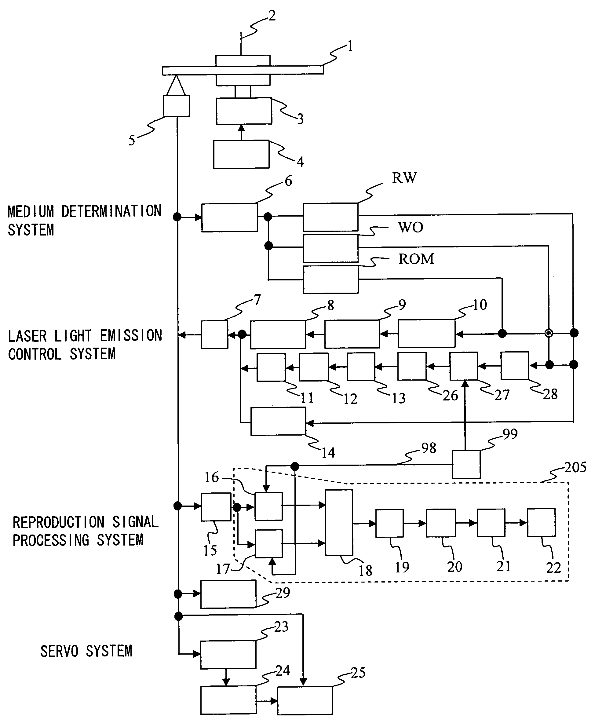
[0046]FIG. 1 shows a block diagram of an example of an optical information recording / reproducing apparatus according to the present invention. In FIG. 1, numeral 1 denotes an optical information recording medium, numeral 2 denotes a spindle, numeral 3 denotes a spindle motor, numeral 4 denotes a motor circuit control means, numeral 5 denotes a pick-up, numeral 6 denotes a medium determination means, numeral 7 denotes a laser driver, numeral 8 denotes a reproduction power DC amplifier, numeral 9 denotes a reproduction peak power determination means, numeral 10 denotes a reproduction bias power determination means, numeral 11 is a recording power DC amplifier, numeral 12 denotes a recording peak power determination means, numeral 13 denotes a recording peak power ratio determination means, numeral 14 denotes an erase power DC amplifier, numeral 15 denotes a reproduction signal detecting means, numeral 16 denotes a peak sampling means, numeral 17 denotes a bias sampling means, numeral ...

example 2

[0090]Pulse reproduction will be reviewed from the viewpoint of signal response characteristics. FIG. 8 shows a diagram in which reflectivity R is a function of temperature T and the temperature dependence of a change ΔR in reflectivity is normalized by reflectivity Ro (30° C.) at 30° C. Reflectivity R(T) at temperature T can be expressed using the following equation with the change ΔR (T) in reflectivity:

R(T)=Ro(30° C.)·(1+ΔR(T))   (5)

[0091]Temperature T on a disk surface varies depending on a point (x, y) on the disk because it is irradiated with an optical spot, and therefore, reflectivity varies at each point (x, y) on the disk surface. When a disk having reflectivity R (x, y, T) is irradiated with a spot distribution S (x, y), its reflective spot distribution I (x, y) becomes a function of temperature as shown in the following equation:

I(x, y, T)=S(x, y)R(x, y, T)   (6)

[0092]It can be assumed that the reflectivity is equal to Ro near the temperature 30 degrees, irrespective of ...

example 3

[0096]In the foregoing example, the response characteristics of super-resolution were improved with pulse reproduction signals alone. However, since the gain becomes large at midrange frequencies, it can be assumed that noise may increase at midrange frequencies and an overall signal-to-noise ratio may decrease. Thus, another example for correction using normal reproduction signals will be proposed. In FIG. 16, given that G(x, y) is the distribution of the increased temperature region on the super-resolution film, equation (8) can be derived, and reflection spot distribution I(x, y) can be expressed by equation (9).

R(x,y)=Ro·(1-G(x,y))(8)I(x,y)=S(x,y)·Ro·(1-G(x,y))=Ro·(S(x,y)-S(x,y)·G(x,y))(9)

[0097]In a current optical disk signal processing, a reproduction signal is deemed as a superposition of responses determined by an optical spot and a unit mark, and partial response or maximum likelihood detection is carried out. Thus, it is preferable to optimize the responses of the spot and...


PUM


Abstract

There is provided an optical information recording/reproducing apparatus capable of obtaining a high super-resolution effect using an optical information recording medium in which a super-resolution thin film is formed. An optical information recording medium 1 having a super-resolution layer is irradiated with a laser light in a light emission pattern such that a bias light emission portion that does not cause the super-resolution layer to be in the state of super-resolution and a pulse light emission portion that causes the super-resolution layer to be in the state of super-resolution alternatively appear, and reflected light is detected. A reproduction signal based on the pulse light emission portion and a reproduction signal based on the bias light emission portion are acquired. The results obtained by performing an arithmetic processing on the reproduction signal based on the bias light emission portion and the reproduction signal based on the pulse light emission portion are outputted as reproduction data.

Description

CLAIM OF PRIORITY[0001]The present application claims priority from Japanese application JP 2006-144262 filed on May 24, 2006, the content of which is hereby incorporated by reference into this application.BACKGROUND OF THE INVENTION[0002]1. Field of the Invention[0003]The present invention relates to an information reproducing apparatus and an information reproducing method for reproducing information from a large-capacity optical information recording medium having a high super-resolution effect.[0004]2. Background Art[0005]With the recent development of the information society involving optical communications, the construction of a communication system that enables high-speed communication of large-capacity information is being demanded. As an optical device indispensable for achieving such large-capacity, high-speed optical communication, an optical information recording / reproducing apparatus for storing large-capacity optical information is used. Further, in association with hi...

Claims


Application Information

Patent Timeline
IPC IPC(8): G11B7/0045
CPCG11B7/005G11B7/259G11B7/24
Inventor MAEDA, TAKESHI
Owner HITACHI CONSUMER ELECTRONICS CORP
Why Eureka
Try Eureka