Radiation resistant single-mode optical fiber and method of manufacturing thereof

a single-mode optical fiber and radiation-resistant technology, applied in the field of silicon glass optical fiber, can solve problems such as loss in the amount of transmitted light (induced loss)

Active Publication Date: 2007-11-29
THE FUJIKURA CABLE WORKS LTD
View PDF5 Cites 25 Cited by
  • Summary
  • Abstract
  • Description
  • Claims
  • Application Information

AI Technical Summary

Benefits of technology

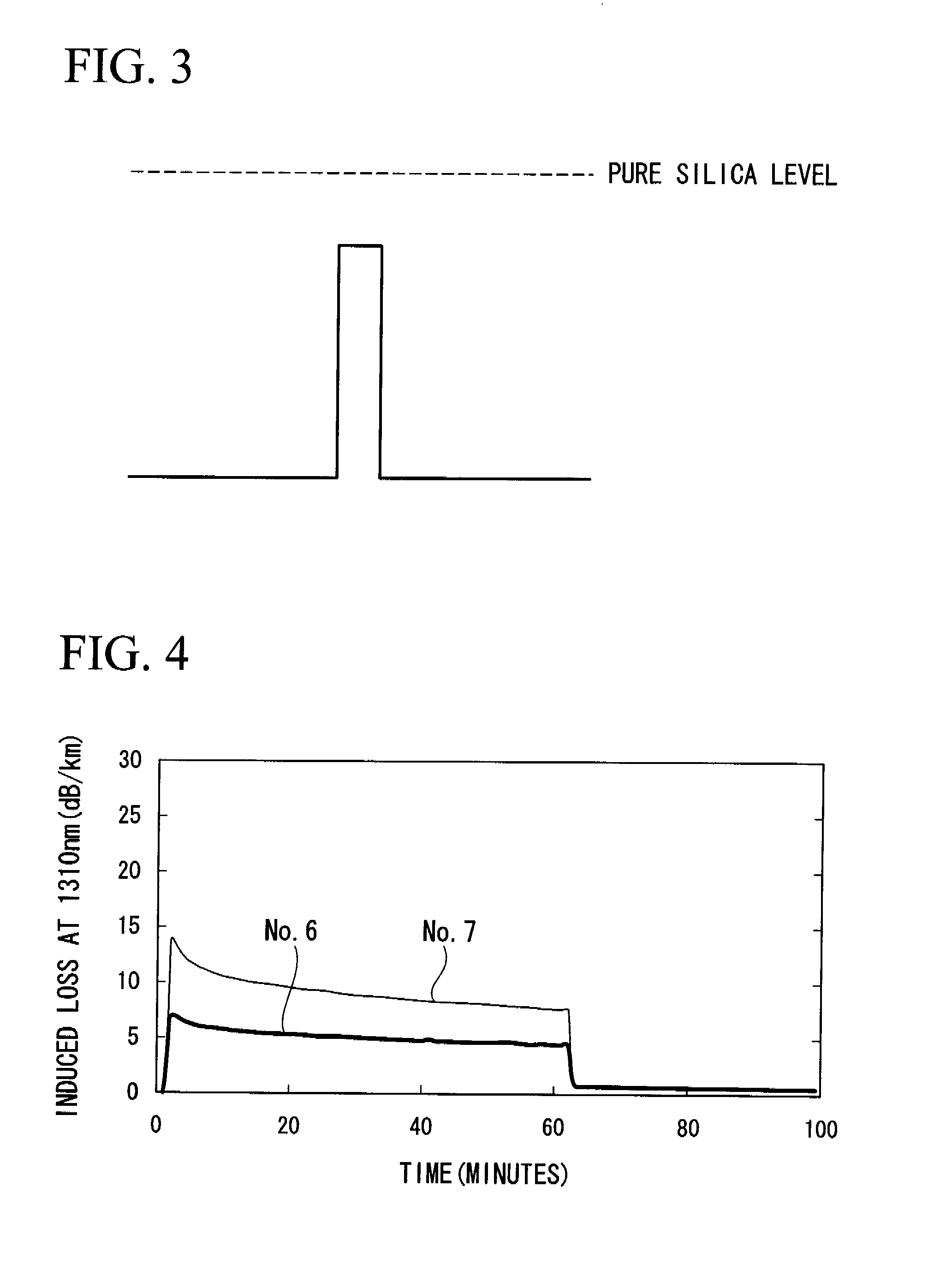
[0024]Because exemplary embodiments of the present invention relate to a radiation resistant single-mode optical fiber composed of a core and a cladding, each made of fluorine-doped silica glass, which optical fiber is characterized in that a chlorine concentration of the core is at least 0.01 ppm, a relative refractive index difference of the core based on the refractive index for silica is between −0.30% and −0.10% , a relative refractive index difference of the core based on the refractive index for the cladding is between 0.3% and 0.5%, a cutoff wavelength is 1.27 μm or below, and a bending loss at a wavelength of 1.3 μm and a bending diameter of 20 mm is 0.5 dB / m or less, the radiation resistant single-mode optical fiber has a low initial loss and experiences minimal loss following exposure to a radiation environment.

Problems solved by technology

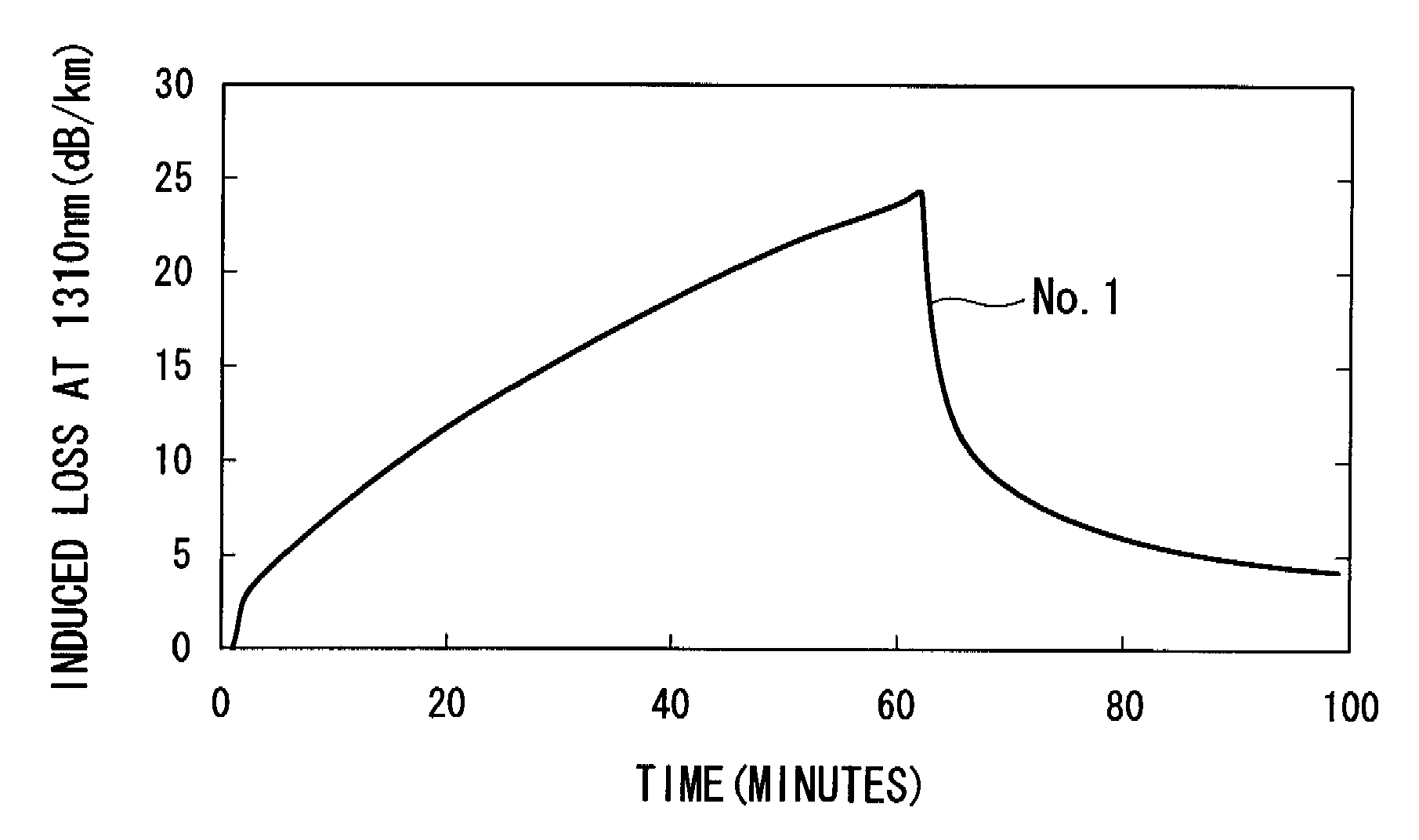
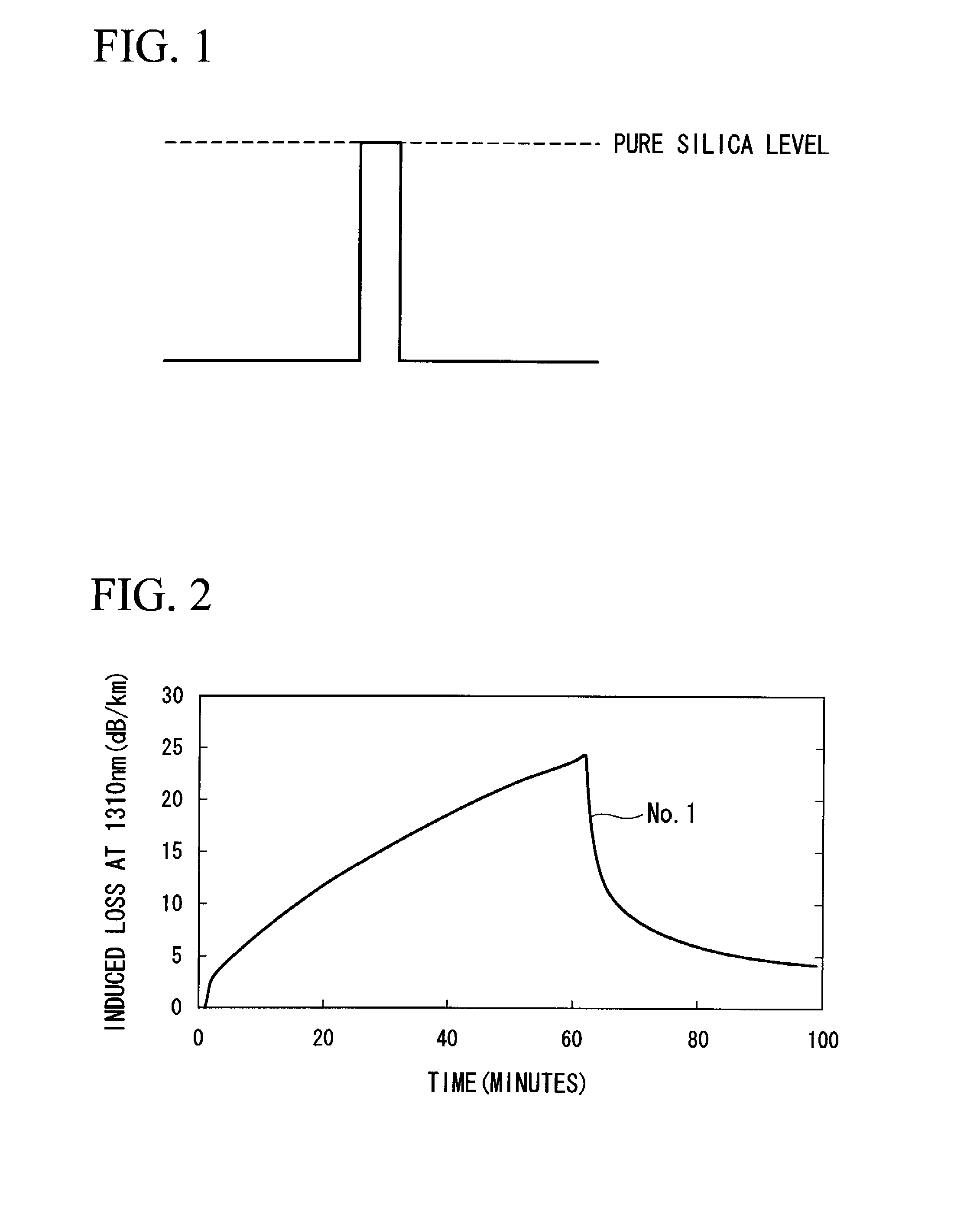
When silica glass optical fibers are used in a radiation environment, a loss in the amount of transmitted light (induced loss) arises due to the radiation environment.

Method used


Image

  • Radiation resistant single-mode optical fiber and method of manufacturing thereof
  • Radiation resistant single-mode optical fiber and method of manufacturing thereof
  • Radiation resistant single-mode optical fiber and method of manufacturing thereof

Examples


example 2

[0050]Silica soot was produced by a VAD method. The silica soot was dehydrated in a 1000° C. atmosphere of helium gas (4 liters) and chlorine gas (160 cc), following which fluorine was added in an atmosphere of helium gas (4 liters) and fluorine (10 cc), and the silica soot was sintered in a 1450° C. atmosphere. The resulting glass was then drawn and silica glass was applied to the outside vapor deposition so as to obtain a given cladding to core diameter ratio.

[0051]This was followed by dehydration in a 1000° C. atmosphere of helium gas (4 liters) and chlorine gas (160 cc), following which fluorine was added in an atmosphere of helium gas (4 liters) and fluorine (2.7 liters), and the silica soot was sintered at 1350° C. The outside vapor deposition method of fluorine doped silica glass was again carried out, yielding an optical fiber preform having a cladding to core diameter ratio (r2 / r1) of 14 and a core relative refractive index difference based on the refractive index for the c...

example 3

[0055]A silica soot was produced by a VAD method. This silica soot was dehydrated in a 1000° C. atmosphere of (4 liters) and chlorine gas (160 cc), then sintered in a 1300° C. atmosphere of helium gas (4 liters) to which 180 cc of SiF4 gas was added. The resulting glass was drawn, and the fluorine doped silica glass was applied to the outside vapor deposition.

[0056]This was followed by dehydration in a 1000° C. atmosphere of helium gas (4 liters) and chlorine gas (160 cc), and sintered in an atmosphere of helium gas (1 liter) and SiF4 gas (4 liters). Next, the outside vapor deposition method of silica glass was again carried out, yielding an optical fiber preform having a cladding to core diameter ratio (r2 / r1) of 14 and a core relative refractive index difference based on the refractive index for the cladding of 0.35%.

[0057]The optical fiber preform was drawn (spun) at a fiber drawing tension of 0.25 N and a fiber drawing speed of 100 m / min, then coated to a diameter of 250 μm with...


PUM

PropertyMeasurementUnit
bending diameteraaaaaaaaaa
cutoff wavelengthaaaaaaaaaa

Abstract

A radiation resistant single-mode optical fiber has a core and a cladding, each made of fluorine-doped silica glass, in which a chlorine concentration of the core is at least 0.01 ppm, a relative refractive index difference of the core based on the refractive index for silica is between −0.30 and −0.10%, a relative refractive index difference of the core based on the refractive index for the cladding is between 0.3% and 0.5%, a cutoff wavelength is 1.27 μm or below, and a bending loss at a wavelength of 1.3 μm and a bending diameter of 20 mm is 0.5 dB/m or less.

Description

CROSS-REFERENCE TO RELATED APPLICATIONS[0001]This application claims priority from Japanese Patent Application No. 2006-112013, filed Apr. 14, 2006, the contents of which are incorporated herein by reference.BACKGROUND OF THE INVENTION[0002]1. Field of the Invention[0003]The present invention relates to a silica glass optical fiber. More specifically, it relates to a radiation resistant single-mode optical fiber which has a low transmission loss even in an environment where it is exposed to radiation, and which experiences a rapid recovery from transmission loss when placed in a radiation-free environment following exposure to a radiation environment.[0004]2. Related Art[0005]When silica glass optical fibers are used in a radiation environment, a loss in the amount of transmitted light (induced loss) arises due to the radiation environment. Optical absorption in the ultraviolet and visible light regions is known to arise due to dopants such as germanium, which are generally used to ...

Claims


Application Information

Patent Timeline
Patent Type & Authority Applications(United States)
IPC IPC(8): G02B6/00
CPCC03B37/01446C03B37/01453G02B6/02C03B2201/20C03C13/046C03B2201/12
Inventor AIKAWA, KAZUHIKOIZOE, KATSUAKISHAMOTO, NAOKIKUDOH, MANABUTSUMANUMA, TAKASHI
Owner THE FUJIKURA CABLE WORKS LTD
Why Eureka
Try Eureka