Oxynitride phosphor and light emitting device

a technology of oxynitride phosphor and light emitting device, which is applied in the direction of discharge tube/lamp details, light sources, electrical apparatus, etc., can solve the problems of 510 nm, insufficient stability, and excellent emission efficiency of phosphor, and achieve the effect of improving the emission efficiency of the first phosphor

Inactive Publication Date: 2007-12-06
SHARP KK +1
View PDF1 Cites 39 Cited by
  • Summary
  • Abstract
  • Description
  • Claims
  • Application Information

AI Technical Summary

Benefits of technology

[0027]According to the light emitting device of the present invention in which an oxynitride phosphor of the present invention is used as a first phosphor and a second phosphor emitting a light having a longer wavelength than the light emitted by the first phosphor is combined therewith, the first phosphor has a low ...

Problems solved by technology

However, a phosphor having excellent emission efficiency of a light of blue to blue-viol...

Method used


Image

  • Oxynitride phosphor and light emitting device
  • Oxynitride phosphor and light emitting device
  • Oxynitride phosphor and light emitting device

Examples


examples 1 to 7

, COMPARATIVE EXAMPLES 1, 2

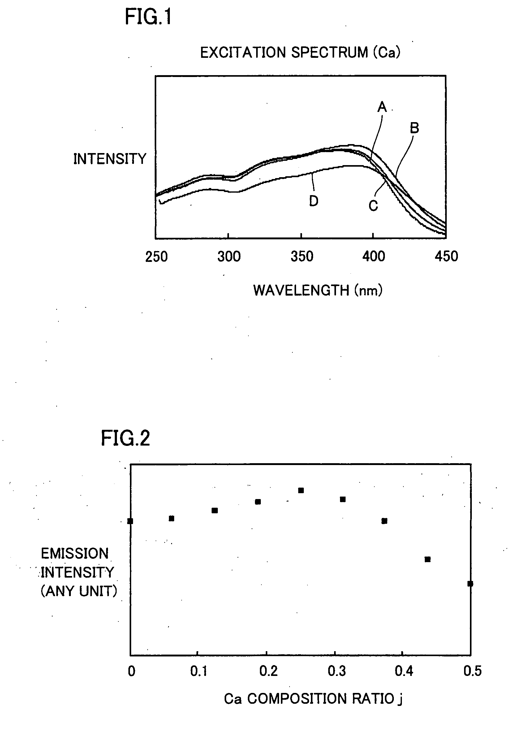
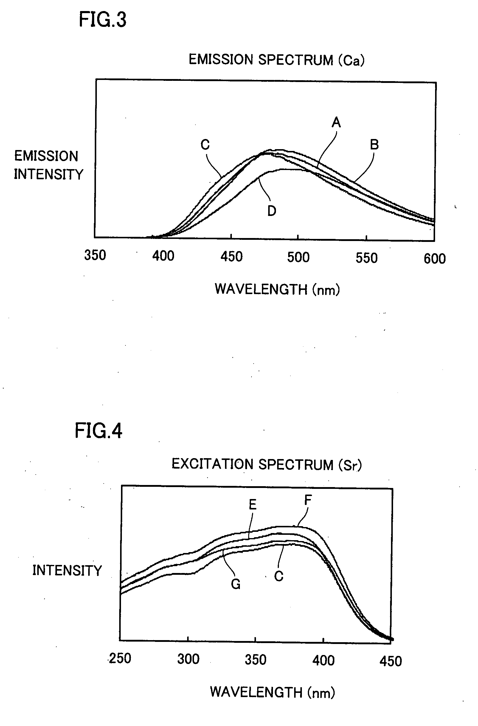
[0120]Samples of Examples 1 to 5 represented by a composition formula La0.5−jCajCe0.5SibAlcOdNe and each having a different composition ratio j of Ca in the range of 0

[0121]A silicon nitride powder having an average particle diameter of 0.5 μm and an oxygen content of 0.93% by weight and an α-type content of 92%, an aluminum nitride powder, calcium carbonate powder, a lanthanum oxide powder, and a cerium oxide powder were weighted and mixed so as to be the material proportions (% by weight) described in Table 2, respectively. This mixed powder was put in a crucible made of boron nitride and the crucible was introduced in a graphite resistance-heating-type electric furnace.

TABLE 2Si3N4AlNCaCO3La2O3CeO2Comparative4.83716.9630.0001.6851.781Example 1Example 14.93416.5551.3001.4861.794Example 25.03316.1422.6301.2831.807Exam...

examples 15 to 22

[0134]Samples of Examples 15 to 19 represented by a composition formula La0.5−jBajCe0.5SibAlcOdNe and each having a different composition ratio j of Ba in the range of 0

[0135]A silicon nitride powder having an average particle diameter of 0.5 μm and an oxygen content of 0.93% by weight and an α-type content of 92%, an aluminum nitride powder, a barium carbonate powder, a lanthanum oxide powder, and a cerium oxide powder were weighted and mixed so as to be the material proportions (% by weight) described in Table 6, respectively. This mixed powder was put in a crucible made of boron nitride and the crucible was introduced in a graphite resistance-heating-type electric furnace.

TABLE 6Si3N4AlNBaCO3La2O3CeO2Example 154.8551.6660.1271.5761.776Example 164.8731.6350.2541.4671.772Example 174.8901.6040.3801.3591.767Example 184.9071.5740.5051.2511.763Example 194.9421.5140.7541...

example 23

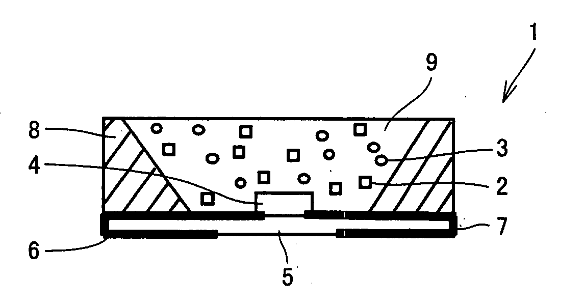
[0144]Light emitting device 1 of the example shown in FIG. 12 was produced. As first phosphor 2, the oxynitride phosphor (blue phosphor) of the present invention that was obtained in Example 11 was used, and as second phosphor 3, α-Sialon phosphor (yellow phosphor) of the composition formula Ca0.93Eu0.07Si9Al3ON15 was used, and the emission color of the light emitting device was set to be white. These phosphors were mixed in a proportion (weight ratio) of blue phosphor:yellow phosphor=16:6, and as sealing member 9, a silicone resin was used and the phosphors were dispersed and sealed in the resin. Moreover, as semiconductor light emitting element 4, InGaN-based semiconductor LED having an emission peak wavelength of 405 nm was used.

[0145]The blue phosphor obtained in Example 11 that was used as first phosphor 2 in the present Example had a small light absorbance of 0.2 in a wavelength of 590 nm (yellow) and therefore, absorption of the fluorescence from the combined and used yellow ...


PUM

PropertyMeasurementUnit
Fractionaaaaaaaaaa
Fractionaaaaaaaaaa
Fractionaaaaaaaaaa

Abstract

The present invention provides an oxynitride phosphor represented by a composition formula M(1)1−jM(2)jSibAlcOdNe (composition formula I) or a composition formula M(1)1−a−jM(2)jCeaSibAlcOdNe (composition formula II) and containing 50% or more of a JEM phase, and a light emitting device including a semiconductor light emitting element emitting an excited light, a first phosphor that is the oxynitride phosphor according to the present invention that absorbs the excited light and emits a fluorescence, and a kind or a plurality of kinds of second phosphor(s) that absorb(s) the excited light and emit(s) a fluorescence having a longer wavelength than the fluorescence emitted by the first phosphor. Thereby, a novel oxynitride phosphor being capable of highly efficiently emitting mainly a light having a wavelength of 510 nm or less and a light emitting device using the same can be provided.

Description

[0001]This nonprovisional application is based on Japanese Patent Application No. 2006-157680 filed with the Japan Patent Office on Jun. 6, 2006, the entire contents of which are hereby incorporated by reference.BACKGROUND OF THE INVENTION[0002]1. Field of the Invention[0003]The present invention relates to an oxynitride phosphor and a light emitting device using the same.[0004]2. Description of the Background Art[0005]A semiconductor light emitting element such as light emitting diode (LED) has an advantage of being compact, requiring little power consumption, and being capable of stably performing high-intensity light emitting. Moreover, a light emitting device for obtaining a visible light by combining a semiconductor light emitting element and a phosphor has an advantage of the semiconductor light emitting element, and furthermore, can emit a light having a color according to purpose of use such as white and therefore, can be utilized for a liquid crystal display, a light source...

Claims


Application Information

Patent Timeline
IPC IPC(8): H01J63/04C09K11/08C09K11/77H01L33/50H01L33/62
CPCC04B35/597H05B33/14C04B2235/3213C04B2235/3215C04B2235/3224C04B2235/3227C04B2235/3229C04B2235/3865C04B2235/3878C04B2235/3895C04B2235/442C04B2235/5445C04B2235/6562C04B2235/766C04B2235/80C09K11/0883C09K11/7774F21K9/00C04B2235/3208H01L33/502C09K11/77748
Inventor TAKAHASHI, KOHSEIHIROSAKI, NAOTO
Owner SHARP KK
Why Eureka
Try Eureka