
Sintered gear and production method therefor

Active Publication Date: 2007-12-13
RESONAC CORP
View PDF3 Cites 15 Cited by
  • Summary
  • Abstract
  • Description
  • Claims
  • Application Information

AI Technical Summary

Benefits of technology

[0011]An object of the present invention is to provide a sintered gear and a production method therefor having several advantages even though conventional materials such as quenched chromium-molybdenum alloy steels for machine structural use are used. That is, in the present invention, compactibility of a powder is improved, the sintered body is easily deformed by plastic working, and hardenability is improved. Although the entire density is as low as possible and the weight is lighted, necessary portions have high density and sufficient strength and wear resistance, and rigidity and durability are totally high. Moreover, in the present invention, mass production efficiency is improved.

Problems solved by technology

Although hot forging may allow producing gears with high density in which there are approximately no pores, the gears may have superfluous quality when the gears are not required to have entirely high density.
Furthermore, weight of the gears is increased and advantages of porous body such as damping capacity and oil impregnation may be lost.
Therefore, hot forging is complicated and the production cost is high.
However, since a tablet-shaped sintered body is compressed and outwardly expanded in a die, thereby closely contacting the body with the die so as to form a tooth profile, high compression pressure is required.
Furthermore, the weights of the sintered bodies are not uniform and there may be cases in which the weight exceeds the predetermined value.
However, the method has a disadvantage in which the rolling needs long time.
Furthermore, in gears with short module, rolling amount is not sufficient, whereby uniform densification is difficult.
Moreover, the method is not suitable for densification of a tooth portion (entire tooth portion) and a shaft hole portion.

Method used


Image

  • Sintered gear and production method therefor
  • Sintered gear and production method therefor
  • Sintered gear and production method therefor

Examples


examples

(1) Raw Powder

[0084]An iron-molybdenum alloy powder in which molybdenum particles are partially diffused and bonded on a surface of an iron powder, 1 mass % of a graphite powder, and 0.6 mass % of ethylene-bis-stearoamide as a lubricant were mixed and a raw powder was prepared.

(2) Compacting

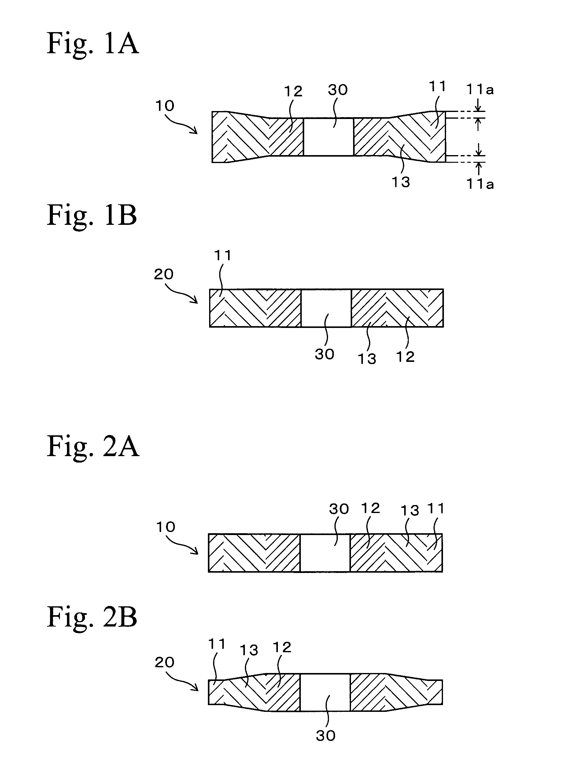
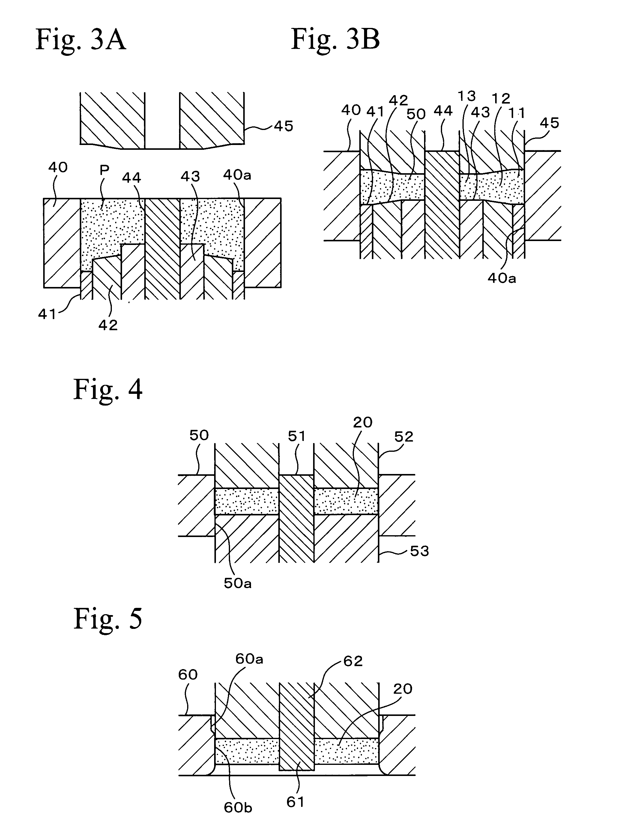
[0085]A compact having a shape of a spur gear was compacted using a die set similar to the die set shown in FIG. 3A. In the compact, the diameter of the tip circle was 60 mm, the number of teeth was 23, the diameter of the shaft hole was 16 mm, and the thickness and the density were set according to FIG. 1A. Specifically, a high density area with a density of 7.3 Mg / m3 and a thickness of 6.36 mm was formed in the entire portion of the tooth portion and an area from the tooth bottom land toward the shaft hole at a depth of 2 mm. A low density area with a density of 6.8 Mg / m3 and a thickness of 6 mm was formed in an area from inner surface of the shaft hole at a depth of 10 mm. An intermediate area...


PUM

PropertyMeasurementUnit
Lengthaaaaaaaaaa
Percent by massaaaaaaaaaa
Thicknessaaaaaaaaaa

Abstract

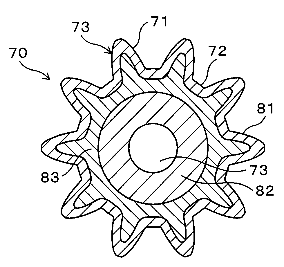
A sintered gear comprises: plural tooth portion having a tooth flank and a tooth bottom land; a high density area formed over entire surface of the tooth portion, the high density area having a density of 7.6 Mg / m3 or more and formed with a depth of 1 mm or more from the surface; a low density area formed in deeper area than the high density area, the low density area having a density of 7.3 Mg / m3 or less; and an intermediate area formed between the high density area and the low density area, the intermediate area having a density gradient in which the density is gradually decreased from the high density area to the low density area.

Description

BACKGROUND OF THE INVENTION[0001]1. Field of the Invention[0002]The present invention relates to sprockets and gears made from sintered metals which are produced by powder metallurgy and production method for the same, and specifically relates to improvements for wear resistance.[0003]2. Description of the Related Art[0004]This kind of sintered gears are largely made from Fe-based alloys, which have densities of about 6.8 to 7.2 Mg / m3 after compacting a powder and sintering the compact. In sprockets and heavy duty gears, wear resistance of a tooth flank is greatly required. In order to meet the requirement, it is effective to heighten density of sintered alloys. In order to enhance the density of Fe-based sintered alloys, hot forging may be effective. Although hot forging may allow producing gears with high density in which there are approximately no pores, the gears may have superfluous quality when the gears are not required to have entirely high density. Furthermore, weight of th...

Claims


Application Information

Patent Timeline
IPC IPC(8): B22F7/00B22F5/08C21D9/32
CPCB22F3/16B22F3/24B22F5/08B22F2003/248F16H55/06Y10T29/49478Y10T74/19949Y10T29/49474Y10T29/49467
Inventor ICHIKAWA, JUNICHIKOHIDA, TOMOYUKINAKATA, KENSUKEARAKAWA, TOMOAKI
Owner RESONAC CORP
Learn More