
Apparatus and Method for NOx Reduction

a technology of emission control device and internal combustion engine, which is applied in the direction of mechanical apparatus, engine components, machines/engines, etc., can solve the problems of nox emissions from internal combustion engine vehicles, put considerable effort toward meeting, and exhaust is too oxygen-rich for three-way catalysts to be effective, so as to achieve the effect of improving the control of emissions

Inactive Publication Date: 2007-12-20
NANOENERGY GROUP UK
View PDF8 Cites 30 Cited by
  • Summary
  • Abstract
  • Description
  • Claims
  • Application Information

AI Technical Summary

Benefits of technology

[0022]It is an object of the present invention to provide a safe, reliable and efficient SCR system for reducing NOx emissions from an internal combustion engine.
[0024]It is another, more specific, object of one aspect of the invention to provide a simple, robust SCR system capable of rapid response time in order to meet transient conditions prevailing in diesel engines.
[0026]It is a yet further and more specific object of the invention to provide an SCR system that enables integration with an engine management system (EMS), thereby avoiding the need for an extra controller. It is a yet further, more specific object of the invention to provide an SCR system with a dedicated controller including the features necessary for SCR, using either dedicated sensors or sharing inputs and outputs where possible with the EMS.
[0030]Additional aspects of the invention relate to control of an exhaust treatment system. One aspect of the control strategy provides for maintaining catalyst temperature within a predetermined range to offer, in particular, improvements in emission control during start-up of diesel engines and thus offer the potential to control emissions to meet expected future regulations.

Problems solved by technology

NOx emissions from vehicles with internal combustion engines are an environmental problem recognized worldwide, Many countries, including the United States, are introducing ever-tightening regulations that limit NOx emissions from vehicles.
Manufacturers and researchers have put considerable effort toward meeting those regulations.
In diesel powered vehicles and vehicles with lean-burn gasoline engines, however, the exhaust is too oxygen-rich for three-way catalysts to be effective.
These techniques alone, however, do not eliminate NOx emissions.
However, NOx reduction efficiency of a typical LNT is lower than that of an SCR system.
Moreover, LNTs are prone to sulfur poisoning that further reduces their effectiveness.
Additionally, constant regeneration of LNTs leads to thermal aging that results in a significant drop of an already low NOx reduction efficiency.
Apart from increasing the system cost, such a method requires the use of at least one exhaust valve.
Experience with similar EGR valves suggests durability and reliability present substantial challenges for such valves.
SCR can achieve NOx reductions in excess of 90%, however, there is concern over the lack of infrastructure for distributing ammonia / urea or a suitable precursor.
Such a change in driver habits is difficult to enforce and, therefore, it leads to a serious compliance issue.
None of these SCR systems that use alternative reductants can match the NOx reduction efficiency of SCR based on urea / ammonia.
Also, the use of hydrocarbons is associated with high fuel penalties.
Moreover, the use of hydrocarbons for an SCR process could result in soot and sulfur deposition on a hot catalyst surface that would lead to a gradual decrease of catalytic activity.
There are no known catalysts that can selectively reduce NOx to N2 using a gas mixture based on hydrogen and carbon monoxide.
High concentration of hydrogen could also generate excessive amount of heat on a catalytic surface and eventually cause sintering and melting of the catalyst.
More importantly, although the patent '958 fully describes an LNT application, it does not teach how to use that invention for an SCR application, nor does it disclose any specific control strategy.
SCR requires a much more complex and precise control than LNT.
Unfortunately diesel exhaust temperatures are often lower than those required for good catalyst efficiency (i.e., below “light-off” level).
However, the use of an electric heater for such a purpose leads to significant electric power consumption.

Method used


Image

  • Apparatus and Method for NOx Reduction
  • Apparatus and Method for NOx Reduction
  • Apparatus and Method for NOx Reduction

Examples


Embodiment Construction

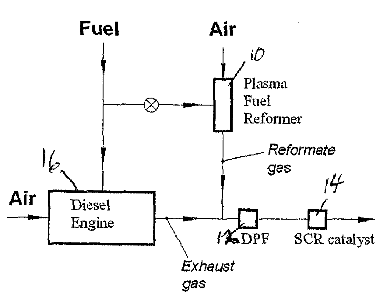
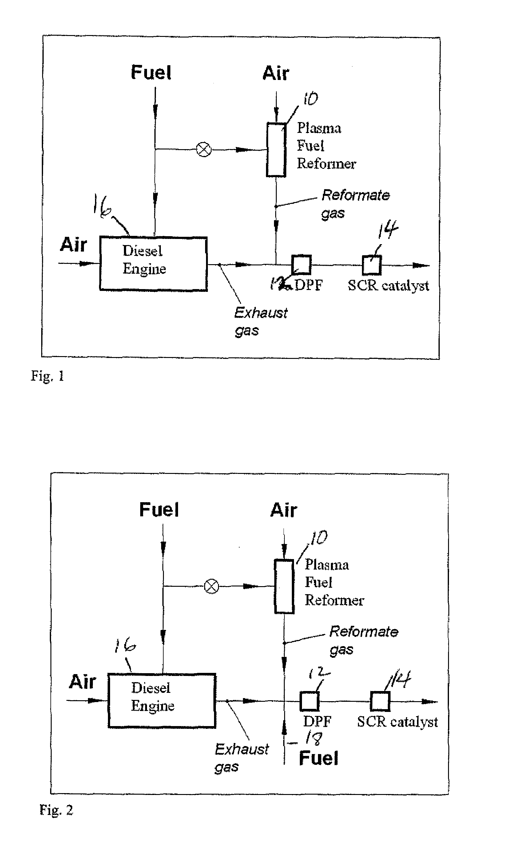
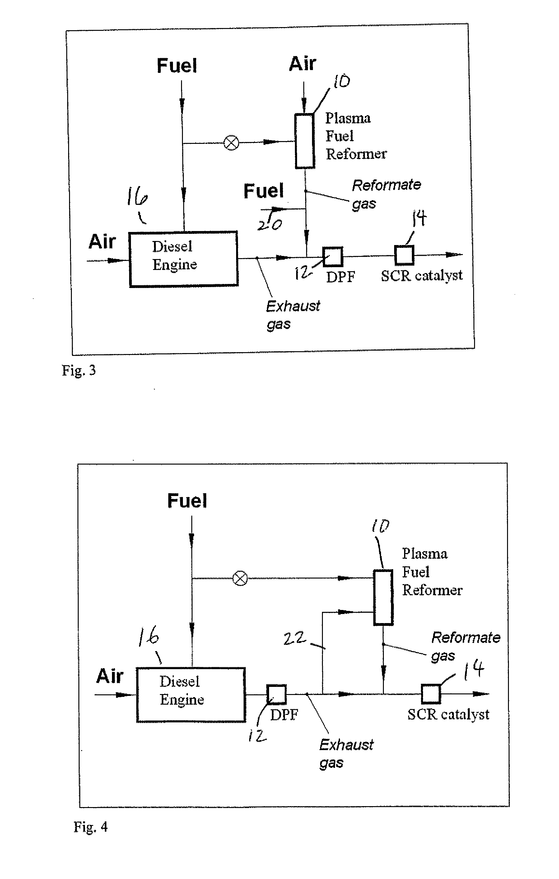
[0040]The proposed system includes an internal combustion engine or a turbine as a source of emissions, a multi-mode plasma fuel processor, selective catalytic reduction (SCR) catalyst and means to implement a predetermined control algorithm.

[0041]The SCR catalyst suitable for this system is usually a silver / alumina catalyst. The fuel processor is able to process liquid hydrocarbon fuel such as diesel or petrol to deliver the reducing agent in required quantity and of required composition while operating in a certain sequence of the following modes in accordance with a predetermined control algorithm: partial oxidation (POX), incomplete pyrolysis, evaporation, combustion, atomization.

[0042]The fuel processor could be based on one of the plasmatrons described in a U.S. patent application No. 11 / 330,515 entitled “Plasma Reformer With Extended Volume Discharge” and U.S. patent application No. 11 / 352,138 entitled “High Enthalpy Low Power Plasma Reformer”.

[0043]The system can also be equ...


PUM


Abstract

Apparatus and method for NOx reduction. A reducing catalyst is provided on a monolith or other suitable catalytic converter element. A multi-mode fuel processor of liquid hydrocarbon fuel is capable of delivering a required quantity and composition of a reducing agent while operating in a desired sequence of the following modes: partial oxidation, incomplete pyrolysis, evaporation, combustion, and atomization. Temperature sensors detect the catalyst temperature and means are provided to introduce the reducing agent into the exhaust stream at a rate correlated to the measured temperature. Means also provided to implement a predetermined control algorithm.

Description

FIELD OF THE INVENTION[0001]The present invention relates to the field of emission control devices for internal combustion engines, especially diesel engines and lean burn gasoline engines.BACKGROUND OF THE INVENTION[0002]NOx emissions from vehicles with internal combustion engines are an environmental problem recognized worldwide, Many countries, including the United States, are introducing ever-tightening regulations that limit NOx emissions from vehicles.[0003]Manufacturers and researchers have put considerable effort toward meeting those regulations. In conventional gasoline powered vehicles that use stoichiometric fuel-air mixtures, three-way catalysts have been shown to control NOx emissions. In diesel powered vehicles and vehicles with lean-burn gasoline engines, however, the exhaust is too oxygen-rich for three-way catalysts to be effective.[0004]Several solutions have been proposed for controlling NOx emissions from diesel powered vehicles and lean-burn gasoline engines. On...

Claims


Application Information

Patent Timeline
Patent Type & Authority Applications(United States)
IPC IPC(8): F01N3/00F01N3/10
CPCF01N3/0253F01N3/035F01N3/206F01N3/2066F01N13/009F01N2240/28F01N2240/30F01N2610/04Y02T10/24F01N3/2073Y02T10/12
Inventor RABINOVICH, ALEXANDERSAMOKHIN, ANDREIALEXEEV, NIKOLAIMURZIN, DMITRYERANEN, KARIARVE, KALLEPESCHKOFF, ALEXANDER
Owner NANOENERGY GROUP UK
Learn More