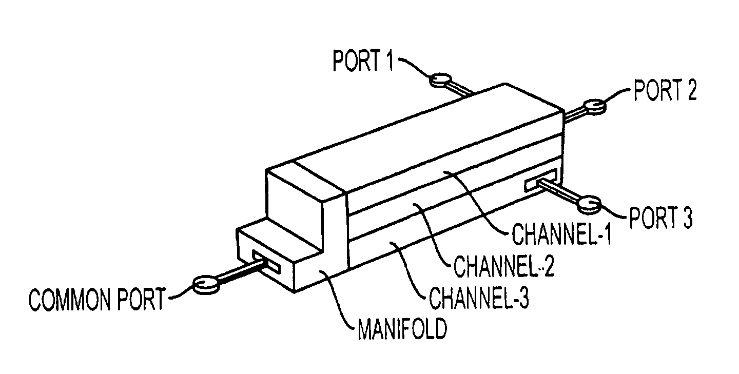
[0009] An array of ridge-waveguide filters, representing a plurality of frequency-band-limited signal channels, may be series-connected through a ridge-waveguide manifold to form a compact frequency
multiplexer with a channeled-signal port for each channel and a composite-signal or common signal port for combined signals of all channels. The main purpose of series-connecting the filters is to allow their waveguide assemblies to be stacked with minimal separations between adjacent
assembly broadsides for maximum compactness. The manifold includes a stack of manifold segments, with one such segment per channel. Each segment comprises a three-way ridge-waveguide junction that is augmented by space-saving quasi-lumped waveguide elements and short waveguide sections to perform required impedance-matching and
coupling functions. The manifold's stacked segments form a tapped non-uniform
trunk line with a first
trunk end, a second
trunk end, and a plurality of trunk channel taps. The first trunk end is connected to the
multiplexer's composite-signal port through a port
coupling network similar in construction to a filter port coupling network, and the second trunk end is terminated in a truncation network. The plurality of manifold trunk channel taps are connected through waveguide port coupling networks to the array of ridge-waveguide filters at their respective first filter waveguide
cascade assembly ends, with the tap port coupling networks considered in the present context to be conceptually associated not with the filters, but with the manifold. The filters connect at their respective second waveguide
cascade assembly ends to the multiplexer's channeled-signal ports through a different set of port coupling networks that typically contain strip- and / or coaxial-to-waveguide transitions.
[0011] The filters of the invention and frequency multiplexers assembled therefrom exhibit low passband
insertion loss, wide upper stopbands, and small physical dimensions, as well as tolerance for high incident power levels. The filters and multiplexers can be designed using commercial, general-purpose
design software, and produced using readily available fabrication techniques. Cost-effective injection molding techniques employing plastics-based, low-loss
dielectric materials and applied to fabricating
dielectric waveguide cores remains a particularly attractive option.
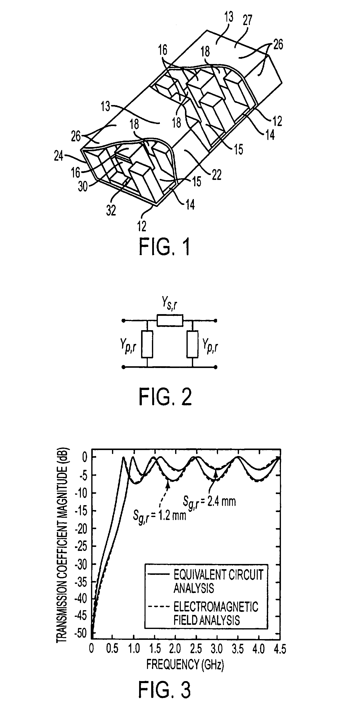
[0013] 1) the realization of a compact
waveguide filter, comprising ridge and evanescent-mode waveguide segments, and further comprising filter port coupling networks that employ ridge-waveguide segments and quasi-lumped waveguide elements, such as irises, transverse
metal fins, posts, and waveguide segments with notched ridges, in order to provide low-loss
impedance matching at the filter's signal ports;
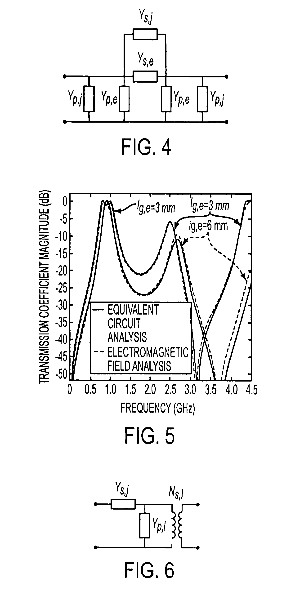
[0016] 4) the realization of evanescent-mode inter-
resonator waveguide coupling segments with waveguide widths of these segments narrower than the width of the main, preferably ridge-type waveguide, so as to raise the cutoff frequencies in the evanescent-mode regions and shorten associated
coupling length between adjacent waveguide resonators;
[0018] 6) the realization of a compact frequency-multiplexer, comprising a manifold and multiple series-connected channel filters, with the manifold employing an array of three-way ridge-waveguide manifold junctions, each augmented with quasi-lumped waveguide circuit components, such as irises, transverse metal fins, posts, and waveguide segments with notched ridges, for the purpose of reducing physical size while still assuring optimum coupling among manifold and associated channel filters, and optimum signal transfer among multiplexer external ports;

