Low dielectric composite materials including high modulus polyolefin fibers

a high modulus polyolefin, low dielectric technology, applied in weaving, high frequency circuit adaptation, synthetic resin layered products, etc., can solve the problems of high cost, inability to meet electrical applications at high usage rates, and often prohibit materials formation and materials costs, etc., to achieve excellent characteristics, improve bonding strength, and promote bond formation

Active Publication Date: 2007-12-20
QUANTUM MATERIALS LLC
View PDF64 Cites 18 Cited by
  • Summary
  • Abstract
  • Description
  • Claims
  • Application Information

AI Technical Summary

Benefits of technology

[0010] Optionally, the binding agent can be a thermoset resin. For instance the thermoset resin can be an epoxy thermoset resin. A thermoset resin can be included in the composite according to any process. For instance, the thermoset resin can be applied to the high modulus polyolefin fibers, to the polyolefin-containing layer(s), and / or to the materials forming a second, different layer of the composite. For instance, the thermoset resin that can bind the layers together can also form a polymeric matrix about the fibers of another layer, e.g., a fiberglass layer.
[0011] In certain embodiments, it can be beneficial to pre-treat the fibers and / or the finished layers prior to securing the layers together so as to improve the bonding strength of the composite. For example, it may be beneficial to oxidize materials of the layers, so as to promote stronger bond formation between the layers and the binding agents. In one embodiment, organic materials, e.g., the polyolefin fibers or fabrics found in the composites, can be oxidized, so as to better bond with resins that can be used as bonding agents. For instance, the materials can be oxidized via a plasma treatment method.
[0012] The composite structures of the invention can exhibit excellent characteristics. For example, the composite structures can have a low average density, such as less than about 1.5 g / cm3. Moreover, the composites can have a low density in combination with high strength characteristics, such as a flexural strength greater than about 80 MPa and / or a flexural modulus greater than about 3 GPa. In addition, the composite structures can have a low dielectric constant, for instance less than about 3.5 in some embodiments, or lower yet in other embodiments, for example, less than about 2.7. As such, the composite materials can be essentially transparent to electromagnetic waves.
[0013] The composite materials can be advantageously utilized in many applications including, for example, in forming circuit boards, radomes, and boat or automobile parts. For instance, the disclosed materials can be utilized in forming radomes or similar structures useful for housing and protecting electromagnetic transmitters and / or receivers for use in weather tracking, aircraft monitoring, or the like. In another embodiment, the low loss composite materials can be used in forming circuit boards, and in one particular embodiment, high frequency circuit boards, i.e., those operating at frequencies greater than about 100 KHz.

Problems solved by technology

For instance, glass fibers can offer excellent tensile strength characteristics, but have a dielectric constant of about 6, and thus are often unsuitable for electrical applications at high usage rates.
These materials can offer excellent strength characteristics but can also be very dense, which can be problematic where weight of the product is a factor, e.g., body armor, automobile parts, boat materials, etc.
Moreover, when the composite materials must be designed to meet high engineering specifications, cost can begin to be a problem.
For instance, in order to meet engineering specifications with regard to flexibility, modulus, density, electrical characteristics, and the like, though various combinations of different materials might be found that can form a composite material to meet the specifications, formation and materials costs often become prohibitive.
Unfortunately, the low strength characteristics of polyolefin yarns and fibers have been such that even when combined with a secondary, relatively strong material in a composite, the strength requirements of the desired application have not been met.
Moreover, as these polymers are generally nonpolar by nature, they often cannot be utilized with known thermoset resins common to fibrous composites, as a strong bond between the thermoset matrix and the polyolefin fiber cannot be formed.

Method used


Image

  • Low dielectric composite materials including high modulus polyolefin fibers
  • Low dielectric composite materials including high modulus polyolefin fibers
  • Low dielectric composite materials including high modulus polyolefin fibers

Examples


example

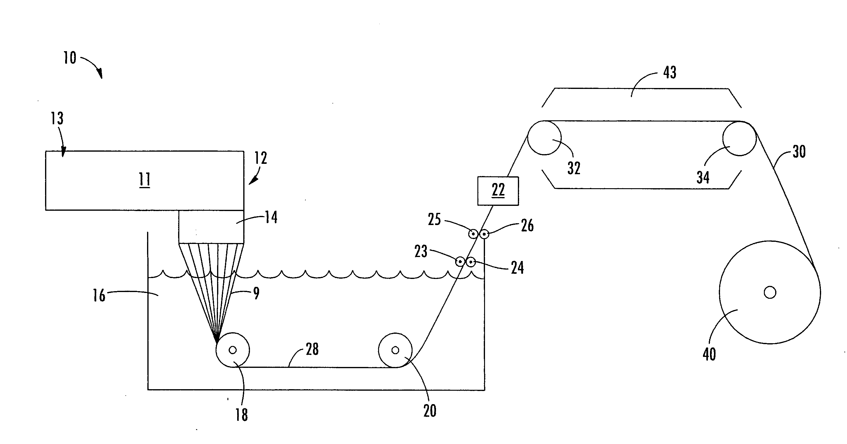
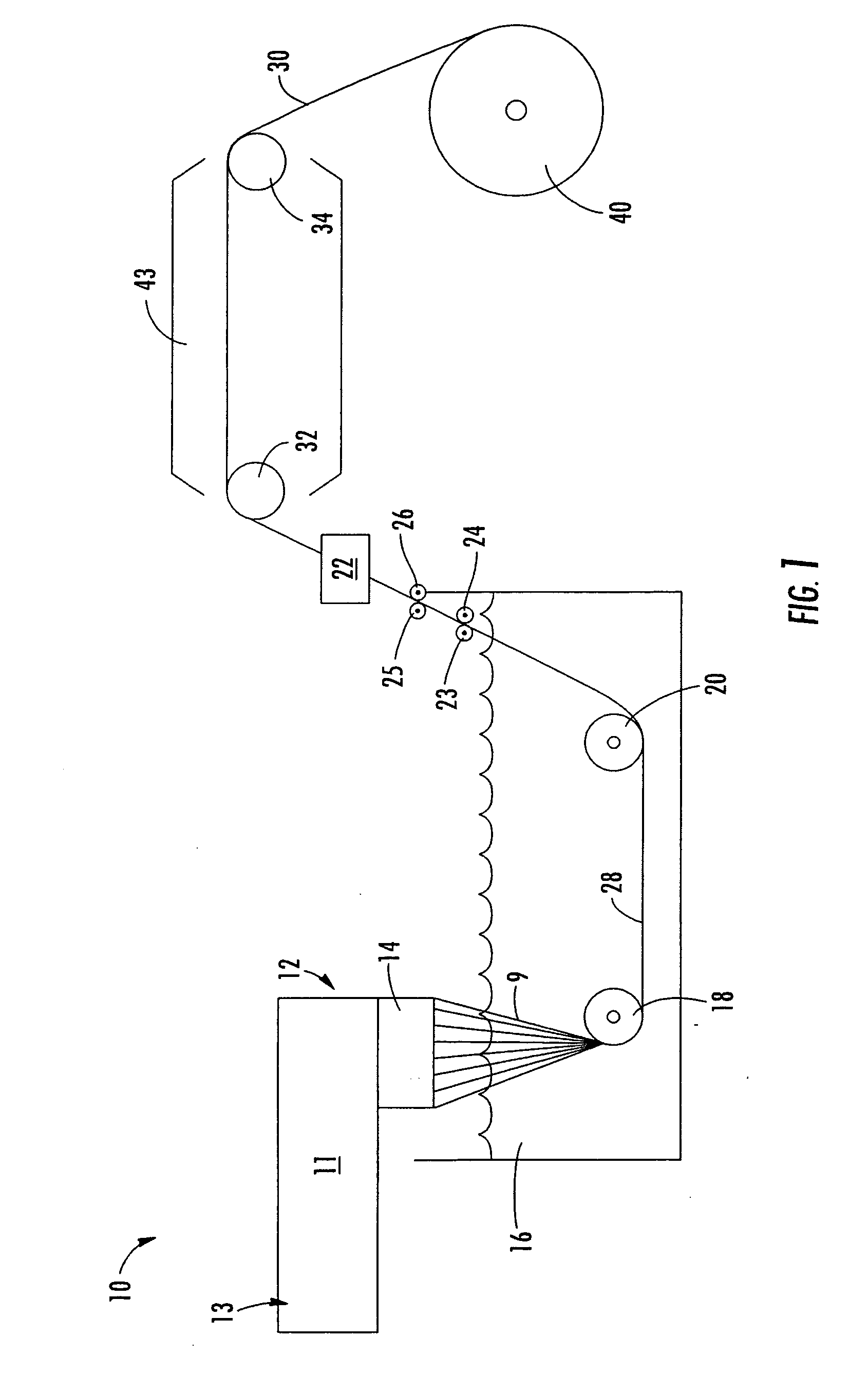
[0105] High modulus, multi-filament polypropylene yarns were formed according to a process such as that illustrated in FIG. 1. These high modulus polypropylene yarns were incorporated into woven fabrics on a narrow loom. The fibers were 1600 denier and 48 filament polypropylene fibers with a modulus of 16 GPa and tenacity of 700 MPa, and were included in the fabric at 12 picks per inch. The weft was made of 1200 denier low modulus polypropylene yarn as are well known in the art. These woven fabrics were then utilized in forming multi-layer composite structures as herein described. These fabric layers are designated HMPP in the tables and figures that follow. Prior to inclusion in the composite structures, these fabrics were plasma treated on an Enercon Plasma3 plasma treatment device using an atmosphere of 80% helium, 20% oxygen at a gap of 0.04 inches, 50 ft / min, and 2 kW power. Prior to this treatment, the dyne level of the fabric was 32 according to Enercon's measurement method, ...

example 2

[0115] Eight layers of HMPP fabric were layered alternating with a polyethylene film, and then compressed at 150° C and 8,000 psi for 5 minutes. The resulting composite had good stiffness and extraordinary toughness.

[0116] In addition, eight layers of HMPP fabric were layered alternating with a random copolymer polypropylene (RCP) film under similar conditions. The resulting compsite was stronger and stiffer than the composite including the polyethylene film, and still extraordinarily tough.

[0117] As a comparative example, eight layers of HMPP fabric were overlaid together with no polymeric binding agent. Three identical structures were compressed at 150° C., 155° C., and 160° C., respectively, and held at 8000 psi for 30 minutes. In each case, the resulting layers peeled apart easily, and at 160° C., the fibers were found to have shrunk to one half of their original length.


PUM

PropertyMeasurementUnit
frequencyaaaaaaaaaa
frequencyaaaaaaaaaa
dielectric constantaaaaaaaaaa

Abstract

Disclosed are composite laminates that can exhibit high strength and/or low dielectric loss and can also be lightweight. The laminates include layers formed of high modulus polyolefin fiber. The fibers can be woven or knit to form a fabric or can be included in a nonwoven fabric that can be one or more layers of the composite structures. The layers including the high modulus polyolefin fibers can include other fibers, such as fiberglass. The composites can also include layers of other materials, for instance layers formed of polyaramids, fiberglass, or carbon fiber wovens or nonwovens. The composites can advantageously be utilized in low loss dielectric applications, such as in forming circuit board substrates, or in applications beneficially combining strength with low weight, such as automobile and boat materials.

Description

BACKGROUND OF THE INVENTION [0001] Composite materials have been developed in many fields in order to obtain products that maintain the desirable characteristics of each component, while minimizing the less desirable characteristics. For instance, glass fibers can offer excellent tensile strength characteristics, but have a dielectric constant of about 6, and thus are often unsuitable for electrical applications at high usage rates. However, glass fibers can be combined with resins, such as certain fluorocarbon resins, that exhibit desirable electrical characteristics to form composite materials having good electrical as well as physical properties. [0002] Other fibrous composite materials, for instance those providing high strength, often include highly engineered fibers such as glass fibers, steel fibers, carbon fibers, Kevlar® fibers (poly-paraphenylene terephthalamide), and the like, held in a stable matrix. These materials can offer excellent strength characteristics but can al...

Claims


Application Information

Patent Timeline
Patent Type & Authority Applications(United States)
IPC IPC(8): D03D15/00A01K1/015B32B5/26B32B27/12D04H13/00D02G3/00B32B9/00H01Q1/42
CPCB29K2223/12B32B5/28D04H13/002D04H13/007H01Q1/422Y10T428/2913H05K1/0366H05K2201/0158H05K2201/0278Y10T428/2964H05K1/024Y10T428/249921Y10T428/249924Y10T442/3065Y10T442/3707Y10T442/3854Y10T442/3886
Inventor MORIN, BRIAN G.
Owner QUANTUM MATERIALS LLC
Why Eureka
Try Eureka