Super-Resolution Microscope

a super-resolution, microscope technology, applied in the field of microscopes, can solve the problems of inability to accurately identify the chemical composition of samples, inability to theoretically expect spatial resolution higher than the diffraction limit, and inability to use micro beams, etc., to achieve simple and inexpensive arrangement, easy selection, and high reliability

Active Publication Date: 2007-12-20
EVIDENT CORP +1
View PDF7 Cites 21 Cited by
  • Summary
  • Abstract
  • Description
  • Claims
  • Application Information

AI Technical Summary

Benefits of technology

[0035] According to the present invention, by configuring the microscope to satisfy the above-mentioned specified conditions, a super-resolution microscope can easily be realized, in which the light source of pump light and erase light can be selected easily, a CW laser having high reliability can be used instead of a short pulse laser source, for example, which is difficult to handle, and a super-resolution can be reliably achieved with a simple and inexpensive arrangement.

Problems solved by technology

In this instance, however, an accurate identification of the chemical composition of the sample is not possible because some molecules generally have an overlapped range of the absorption wavelength.
In other words, with the conventional scanning laser microscope or the like, wherein laser beam is focused into a micro beam by a condenser lens to scan over a sample to be observed, the size of the micro beam is limited within a diffraction limit determined by the numerical aperture of the condenser lens and the wavelength of the laser beam, so that a spatial resolution higher than the diffraction limit cannot theoretically be expected.

Method used


Image

  • Super-Resolution Microscope
  • Super-Resolution Microscope
  • Super-Resolution Microscope

Examples


Embodiment Construction

[0053] An embodiment of a super-resolution microscope according to the present invention will be explained below.

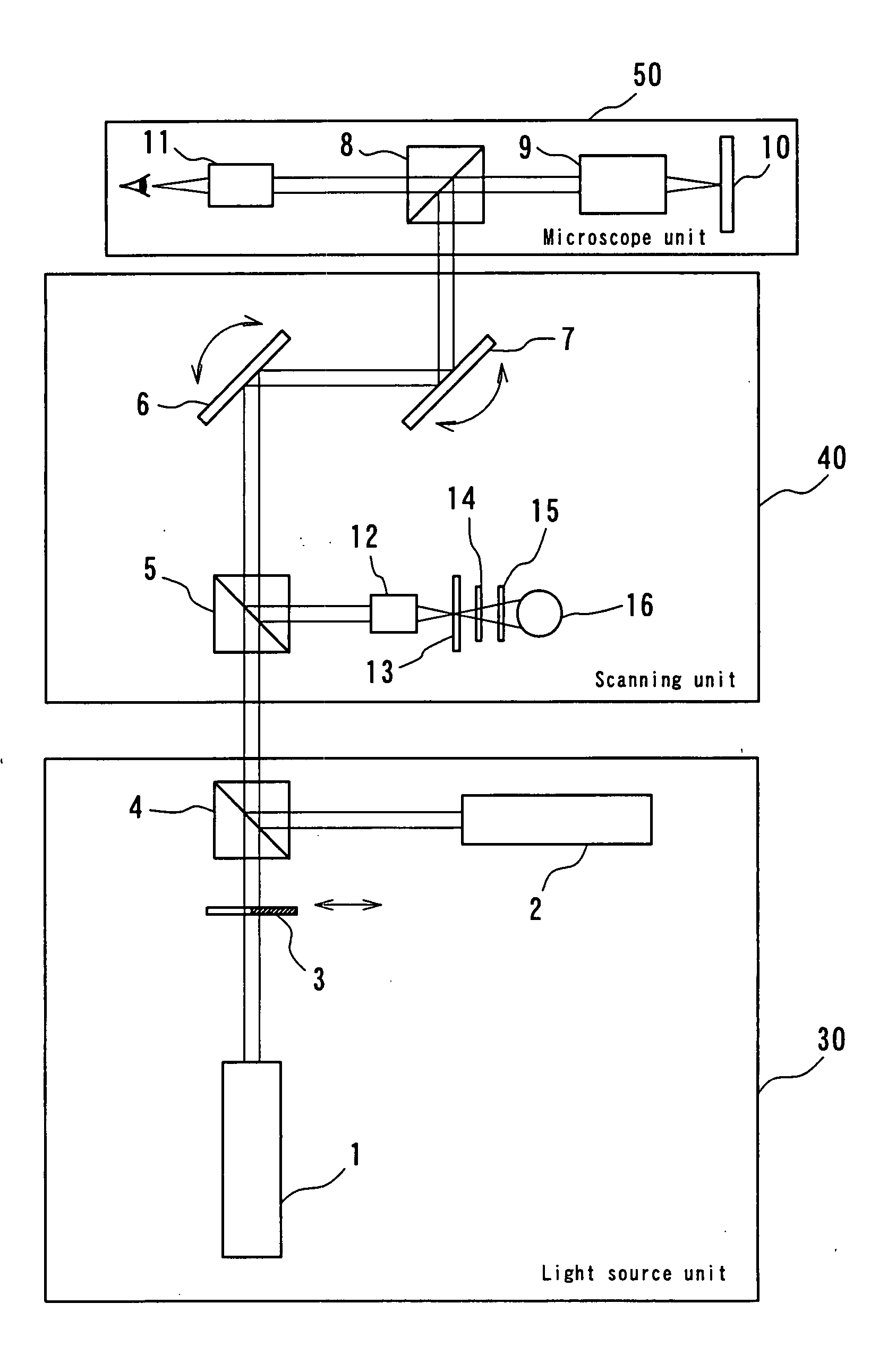
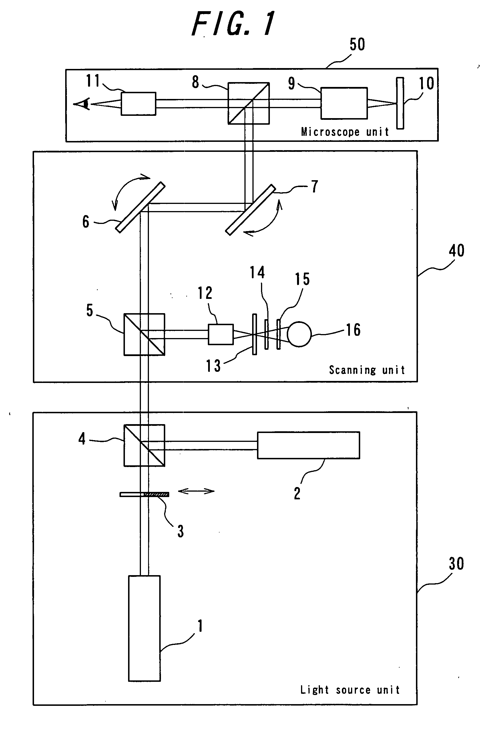
[0054]FIG. 1 shows a configuration of a super-resolution microscope system of according to an embodiment of the present invention. This super-resolution microscope is supposed to be an ordinary laser scanning type fluorescence microscope, and comprised of three independent units, i.e., a light source unit 30, a scanning unit 40 and a microscope unit 50.

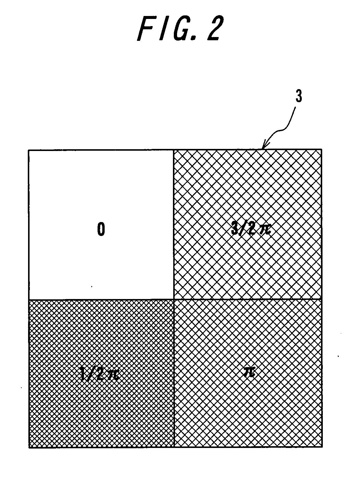
[0055] The light source unit 30 comprises a first light source, for example an LD-excited type mode-locked Nd:YAG laser 2 irradiating a pump light having a wavelength 532 nm as a first coherent light, a second light source, for example a Kr laser 1 irradiating an erase light having a wavelength 647 nm as a second coherent light, a phase plate 3 for spatially modulating the erase light, and a beam combiner 4 for combining the erase light and the pump light. On the surface of the phase plate 3, an optical thin film is evapo...


PUM


Abstract

[Task] To provide a super-resolution microscope whereby the light source of pump light and erase light can be selected easily and a super-resolution can be reliably achieved through a simple and inexpensive arrangement.
[Solution of the Task] A super-resolution microscope includes an optical system (3, 4, 9) for combining a part of a first coherent light from a first light source (2) and a part of a second coherent light from a second light source (1) and focusing the coherent lights onto a sample (10), scanning means (6, 7) for scanning the coherent lights, and detecting means (16) for detecting an optical response signal from the sample (10). The microscope is configured so as to satisfy the following conditions:
σ01Ipτ≦1, and
0.65(λe/λp)≦τσdipIe
where λp is the wavelength of the first coherent light, λe is the wavelength of the second coherent light, τ is the excited lifetime in which the molecule is excited by the first coherent light from the ground state to the first electron-excited state, Ip is the maximum photon flux on the sample surface of the first coherent light, Ie is the maximum photon flux on the sample surface of the second coherent light, σ01, is the absorption cross-sectional area when the molecule is exited from the ground state to the first electron-excited state, and σdip is the fluorescence suppression cross-sectional area.

Description

TECHNICAL FIELD [0001] The present invention relates to a microscope, and more specifically to a super-resolution microscope of high performance and high functional capability, realizing a high spatial resolution by irradiating a dyed sample with a plurality of lights having different wavelengths generated by a laser source of high performance. BACKGROUND OF THE INVENTION [0002] The technology of optical microscopes dates back centuries, and there have been developed various kinds of microscopes. In recent years, with advances in peripheral technologies including laser technology and electronic image processing technology, microscope systems of even higher functional capability have been developed. [0003] Under such context, there has been proposed a microscope of high functional capability that can even perform a chemical analysis, as well as contrast control of an obtained image, using a double resonance absorption process caused by irradiating a sample with lights of different wa...

Claims


Application Information

Patent Timeline
Patent Type & Authority Applications(United States)
IPC IPC(8): G02B21/06H01S3/00
CPCG01N21/6458G01N2021/6419G02B27/58G02B21/002G02B21/16G01N2021/6439
Inventor IKETAKI, YOSHINORIWATANABE, TAKESHIFUJII, MASAAKI
Owner EVIDENT CORP
Why Eureka
Try Eureka