Honing Feed System Having Full Control of Feed Force, Rate, and Position and Method of Operation of the Same

a honing machine and feed system technology, applied in the direction of process control, process control, instruments, etc., can solve the problems of inability to control the cycle time, excessive wear of abrasives, tool or fixture damage, etc., and achieve the effect of improving the productivity of many honing applications and wide application

Active Publication Date: 2007-12-27
SUNNEN PROD
View PDF9 Cites 36 Cited by
  • Summary
  • Abstract
  • Description
  • Claims
  • Application Information

AI Technical Summary

Benefits of technology

[0017] What is disclosed is a feed system for a honing machine which provides a capability to dynamically correct in real time errors in bore size inferred arising from variations in feed force, and a method of operation of the same, which allows a user to select between rate and force controlled honing modes, which provides one or more of the advantages of both types of feed systems discussed above, and which overcomes one or more of the disadvantages and shortcomings of the systems set forth above. Such a feed system is anticipated to have wide application for many types of honing tools and improve productivity of many honing applications. The system also provides capabilities for automatic rapid automatic bore wall detection, compensation for elasticity of elements of the feed system and honing tool, and automatic tool protection.
[0020] The system of the invention also allows for these two basic modes to be mixed within a honing cycle, e.g. honing at a controlled rate until some condition is met then honing at controlled force until the bore is at final size. Furthermore the system allows for a high degree of flexibility in feed control programming. Parameters such as feed rate, feed force, spindle torque or load, time, number of reciprocation strokes, workpiece temperature, and others can be used in real-time control logic that adapts the controlled feed parameter or even changes the feed control method in a simple or complex programmed manner.
[0022] Another problem that can be resolved or avoided is distortion of workpieces that have non-uniform cross sections. The system can automatically operate to initially remove material at a relatively high feed force or rate, and then, at some predetermined distance before reaching final size, the force or rate can be automatically lowered to a value that relaxes the workpiece distortion and allows for improved bore cylindricity.

Problems solved by technology

Disadvantages include that cycle time cannot be controlled, i.e. stones that glaze will hone with increasingly longer cycle times. And, abrasives make rapid contact with rough or out of round bores causing tool or fixture damage and / or wearing abrasive stones excessively.
Disadvantages include that feed rod force is unknown.
Feed forces can reach levels that endanger the tool, fixture, or operator.
Variations in the pre-process bore size will result in either wasted time or dangerous crash conditions.
Such impact is likely to the damage tool or the workpiece.
And, since the force in the feed rod / wedge is unknown, the elasticity of those elements as well as the elasticity of the entire system introduces an error when inferring bore size from encoder position.
It is not possible to exactly control both feed force and feed rate.
However, if the constant rate system is in control, then there is no means to measure feed force or to correct bore errors caused by variances in feed force.
Also, it is not possible to select the slower system when it is desirable to do so, e.g. to improve bore geometry at the end of the honing cycle.
However, this system includes no means to measure feed force or to correct bore errors caused by variances in feed force.
Also, it is not possible to select the controlled force system other than for the initial rapid expansion of the stones.
However, this includes no means to measure feed force or to correct bore errors caused by variances in feed force.
The torque limit of the motor is roughly equivalent to a limit on feed force, although mechanical inefficiencies limit the accuracy of using of torque limits as feed force limits.
This system also does not include a means to measure feed force or to correct bore errors caused by variances in feed force.
There also appears to be no means to control the honing feed to a desired feed force apart from merely preventing the force from exceeding some limit.
In such a system, feed force is inferred by measurement of hydraulic pressure and subject to errors such as that induced from frictional forces between the hydraulic piston and its bore.
In a limited way this compensates for errors caused by the elasticity of the workpiece and the feed system components, but as the compensation is a static correction based on force measurements in the previous workpiece, it describes no means to dynamically correct for variations encountered with the workpiece currently being honed.
However, in most applications, this assumption cannot be made reliably.
Also, this method makes no suggestion that honing feed force can be controlled throughout the honing cycle.
In all of the above-referenced prior art patents there appears to be no method to dynamically correct in real time for errors in bore size inference that arise due to variations in the feed force.
Also, none of the referenced prior art patents gives the honing machine user the ability to choose between rate controlled mode and force controlled mode or to program a honing cycle to switch between the two modes in a manner that could optimize performance.

Method used


Image

  • Honing Feed System Having Full Control of Feed Force, Rate, and Position and Method of Operation of the Same
  • Honing Feed System Having Full Control of Feed Force, Rate, and Position and Method of Operation of the Same
  • Honing Feed System Having Full Control of Feed Force, Rate, and Position and Method of Operation of the Same

Examples


Embodiment Construction

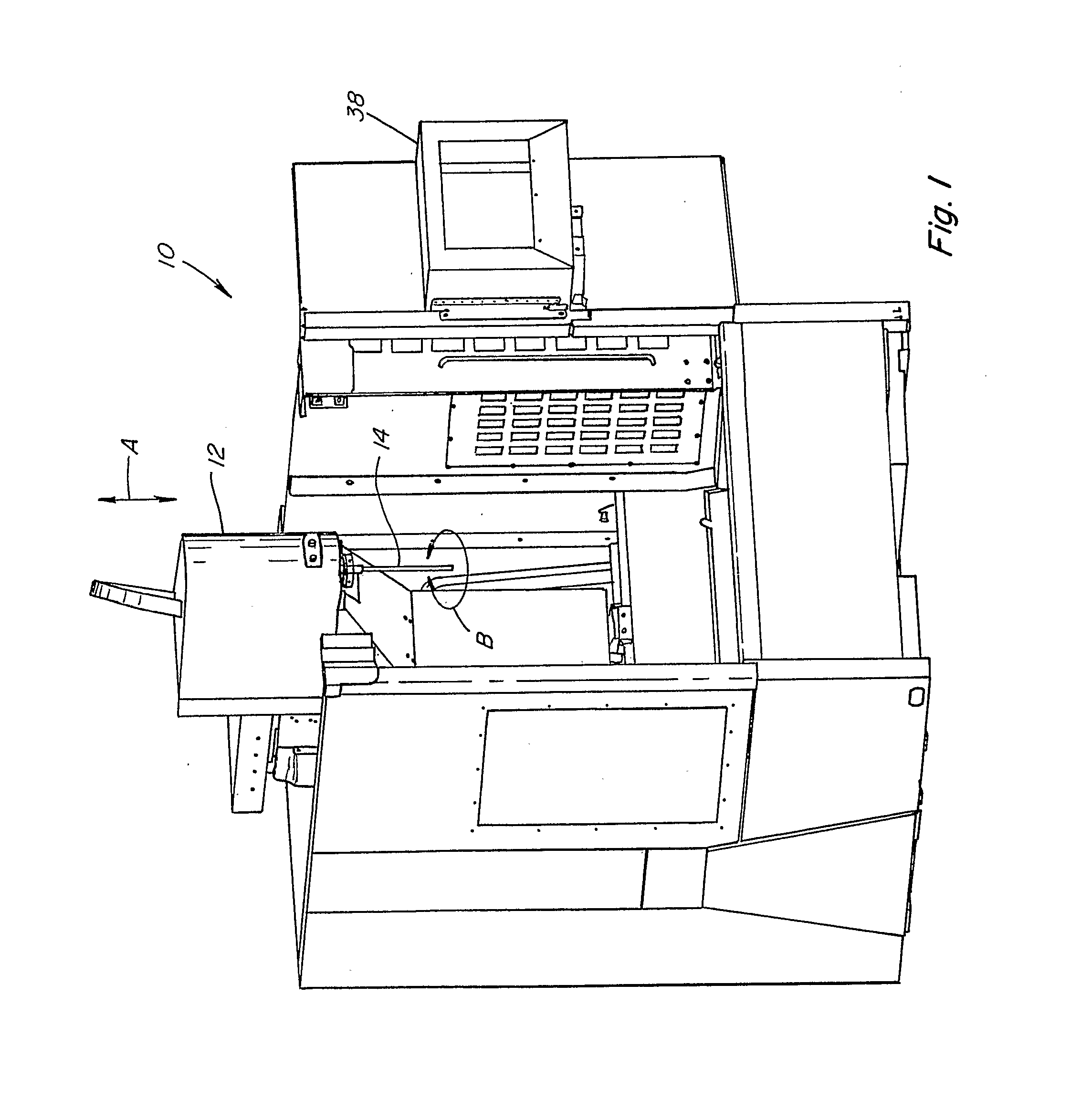
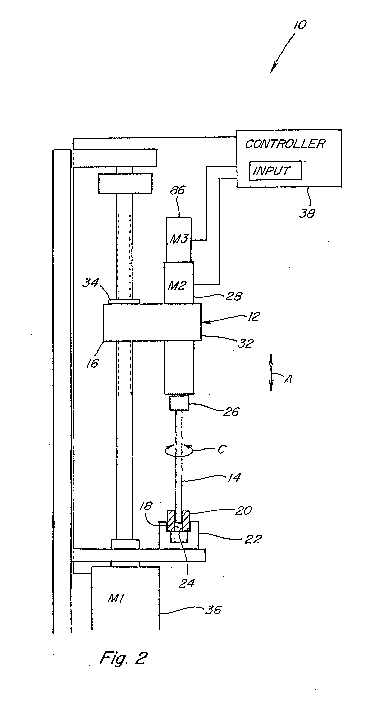
[0036] Referring now to the drawings wherein a preferred embodiment of a feed system and method of operation thereof is shown, in FIG. 1, a representative computer controlled honing machine 10 is shown including aspects of the feed system according to the present invention. Honing machine 10 generally includes a spindle carriage 12 which is movable in a reciprocating stroking action, denoted by arrow A, by a linear motion system such as a conventional motor driven cam linkage mechanism, or a ball screw, roller screw, linear servomotor, rack and pinion, hydraulic cylinder, chain, or belt, under control of a process based main controller 38. Here, carriage 12 is shown supported for reciprocal stroking action in a vertical direction, but it should be understood that stroking in other directions is also contemplated under the present invention. Spindle carriage 12 includes a honing tool 14, which can be of conventional or new construction and operation, generally including an elongate m...


PUM

PropertyMeasurementUnit
feed forceaaaaaaaaaa
elasticityaaaaaaaaaa
diameteraaaaaaaaaa

Abstract

The feed system (30) for a honing machine (10) provides a capability to dynamically correct in real time errors in bore size inferred arising from variations in feed force, and a method of operation of the same. The system (10) allows a user to select between rate and force controlled honing modes, which provides one or more of the advantages of both modes. The system provides capabilities for automatic rapid automatic bore wall detection, compensation for elasticity of elements of the feed system (30) and honing tool (14), and automatic tool protection. The system is automatically operable using feed force, feed rate and positional information for honing a work piece (20) to one or more target parameters, such as one or more in-process sizes and a final size.

Description

[0001] This application claims the benefit of U.S. Provisional Application No. 60 / 607,742, filed Sep. 7, 2004.TECHNICAL FIELD [0002] This invention relates to a feed system for a honing machine, and more particularly, to a feed system automatically operable using feed force, feed rate and positional information for honing a work piece to one or more target parameters, such as one or more in-process sizes and a final size. BACKGROUND ART [0003] Traditional honing feed systems can be classified into two types: 1) Force controlled, and 2) Rate controlled. In a force controlled system, a constant or controlled force is applied to the feed rod / wedge of the honing tool. The force can be applied by a spring, a cylinder, or other means. A measurement system or a mechanical trigger detects when the wedge has reached a point that is either known or inferred to be the finished bore size. In a rate controlled feed system, a motor, typically controlled by feedback from an encoder, moves the feed...

Claims


Application Information

Patent Timeline
Patent Type & Authority Applications(United States)
IPC IPC(8): B24B33/06
CPCB23Q17/2233B24B33/02B24B47/20B24B49/16G05B19/404G05B2219/49356G05B2219/45237G05B2219/49079G05B2219/49099G05B2219/49114G05B2219/49182G05B2219/41109
Inventor CLOUTIER, DANIEL R.HOTH, TIMOTHY P.JACOBSMEYER, RUSSELL L.
Owner SUNNEN PROD
Why Eureka
Try Eureka