Voltammetric Ion Sensor

a technology of ion sensor and voltage, applied in the direction of liquid/fluent solid measurement, instruments, electrochemical variables of materials, etc., can solve the problems of large sample size required for measurement, limited ise minimum size, and unsatisfactory slowness, so as to reduce the response time, the effect of accurate results and the ability to change the response time of the devi

Inactive Publication Date: 2008-01-17
ROCHE DIAGNOSTICS OPERATIONS INC +1
View PDF4 Cites 17 Cited by
  • Summary
  • Abstract
  • Description
  • Claims
  • Application Information

AI Technical Summary

Benefits of technology

[0012] Further, not only is the response time reduced, but the skilled person is provided with the ability to control the response time depending on the specific requirements of the test to be carried out. By altering the support matrix thickness, the response time of the device can be changed, and thus tailored to suit the application.
[0013] One embodiment of the invention, in which the electrochemical reaction is reversible, provides particularly accurate results. This is achieved by applying a scan of the potential to the sensing electrode and determining the potential at which the current peaks occur in both the cathodic and anodic scans. By averaging the two results, a more accurate measurement can be achieved. This is the mid point potential (Em). This embodiment also has the advantage that a reliable measurement can be made even before the system has fully reached chemical equilibrium.
[0014] The method of the invention therefore provides a rapid and reliable detection technique and, through the use of particular ionophores in the support matrix, can be highly selective for the particular ion to be detected. In addition, the presence of the support matrix retains the electroactive species and other substances at the electrode surface and helps to prevent dissolution in the fluid.

Problems solved by technology

The timescale of the measurement is therefore dictated by time to achieve equilibrium and is undesirably slow.
A further difficulty with known ISEs relates to the large sample size required for measurement.
The minimum size of ISE which can be produced is limited by practical requirements.
However, the selectivity of voltammetric sensors is not adequate and their use has not thus far been favoured over ionophore ISEs.

Method used


Image

  • Voltammetric Ion Sensor
  • Voltammetric Ion Sensor
  • Voltammetric Ion Sensor

Examples


example 1

Production of Device

[0069] A conventional three-electrode cell was employed, with 1.5 mm diameter glassy carbon (GC) electrode as the sensing electrode, and a Pt wire as the counter electrode. A Ag / AgCl (3 M NaCl) electrode was used to provide the reference potential scale. The GC sensing electrode was polished with a 0.3 μm Al2O3 (Buehler) slurry, washed successively with water and acetone and dried with tissue paper.

[0070] A coating composition was then prepared by combining 1 ml PVC solution (0.15 g PVC dissolved in 8 ml THF), with 37.5 μl NPOE (plasticizer) which contains 2.5 mM TCNQ (electroactive species), 25 mM valinomycin (ionophore) and 10 mM TBATPB (ionic salt). A small volume (less than 1 μl) of coating solution was introduced on to the surface of the glassy carbon (GC) electrode using a micropipette. The sensor was then left in the air for about 5 minutes to allow the THF to evaporate.

example 2

K+ Sensor

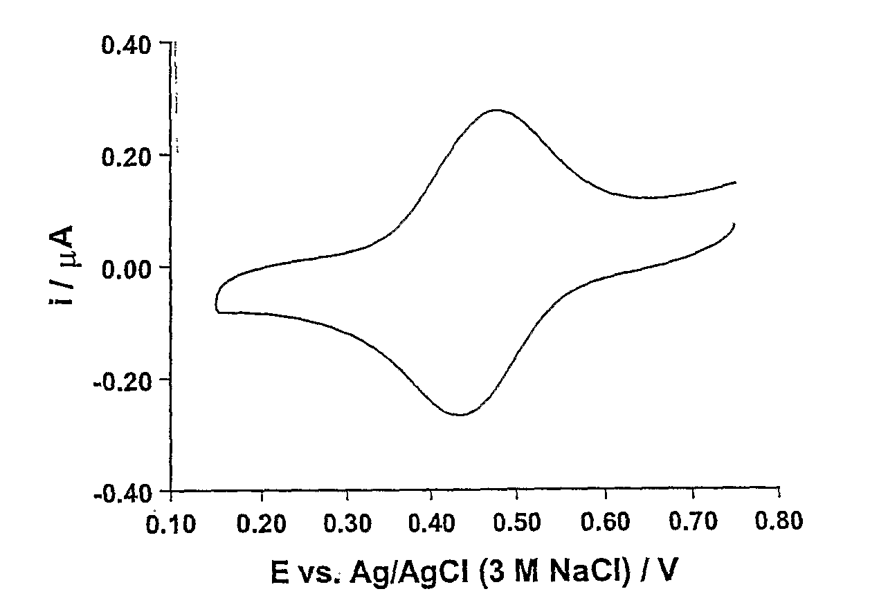
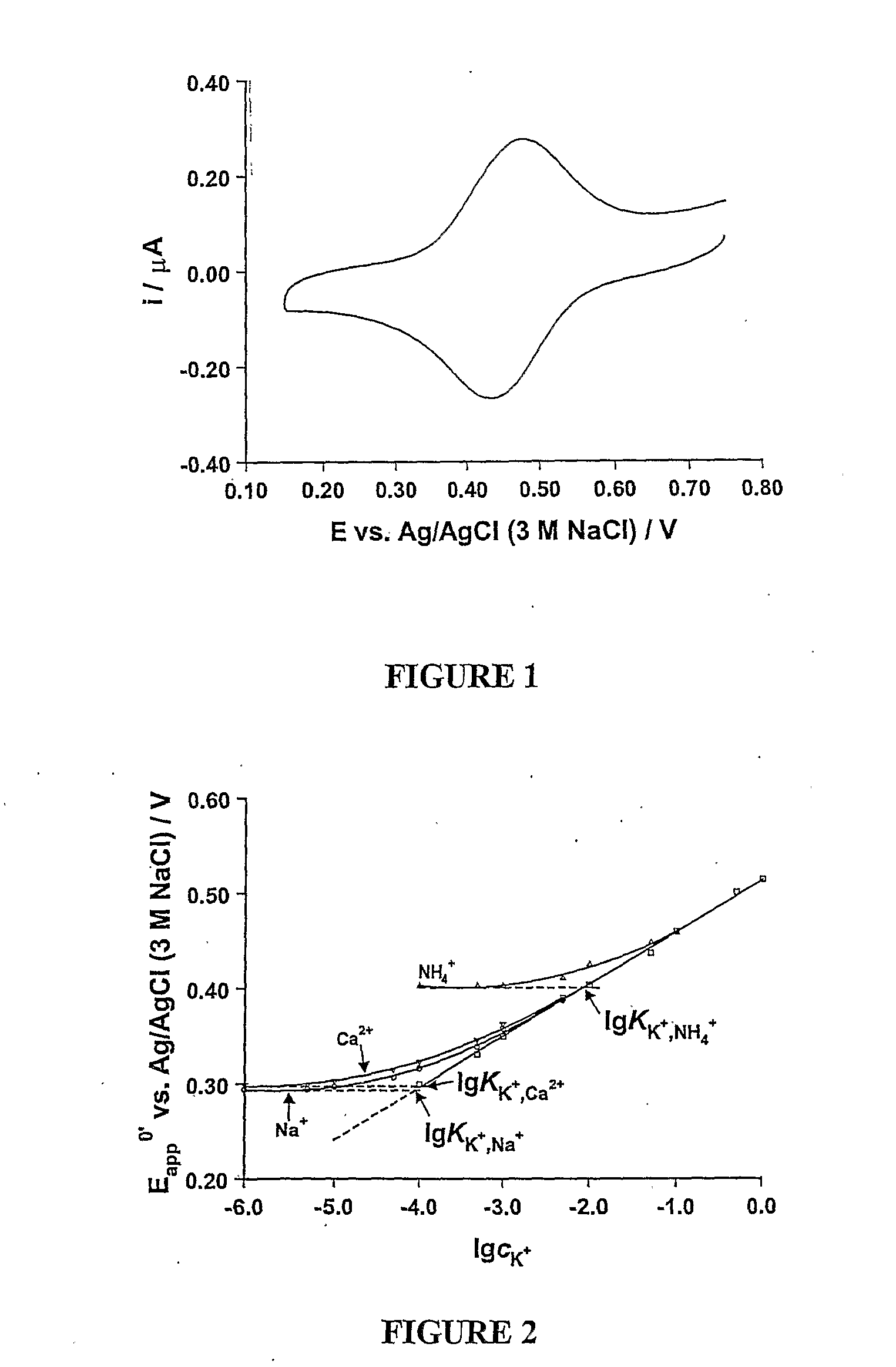
[0071] A measurement was carried out using a 0.1 mol dm−3 solution of KCl as the fluid. The fluid was contacted with the electrodes of a device produced in accordance with Example 1 and a potential scan was applied to the sensing electrode, the scan involving increasing the applied potential from substantially zero to 0.8V and then reducing the applied potential to zero again. The current was measured during application of the scan. A voltammogram showing the results is depicted in FIG. 1. Scan rates of between 10 mVs−1 and 1 Vs−1 were used and the measurement was found to be independent of the scan rate within this range.

[0072] The selectivity of this sensor was determined in relation to Na+, NH4+ and Ca2+ ions using the fixed interference method recommended by IUPAC (Morf: The Principles of Ion Selective Electrodes and of Membrane Transport, Elsevier: Amsterdam, 1981). The concentration of interference ion was fixed at 1.0 mol dm−3 and the concentration of target ion (K...

example 3

Alternative K Sensor

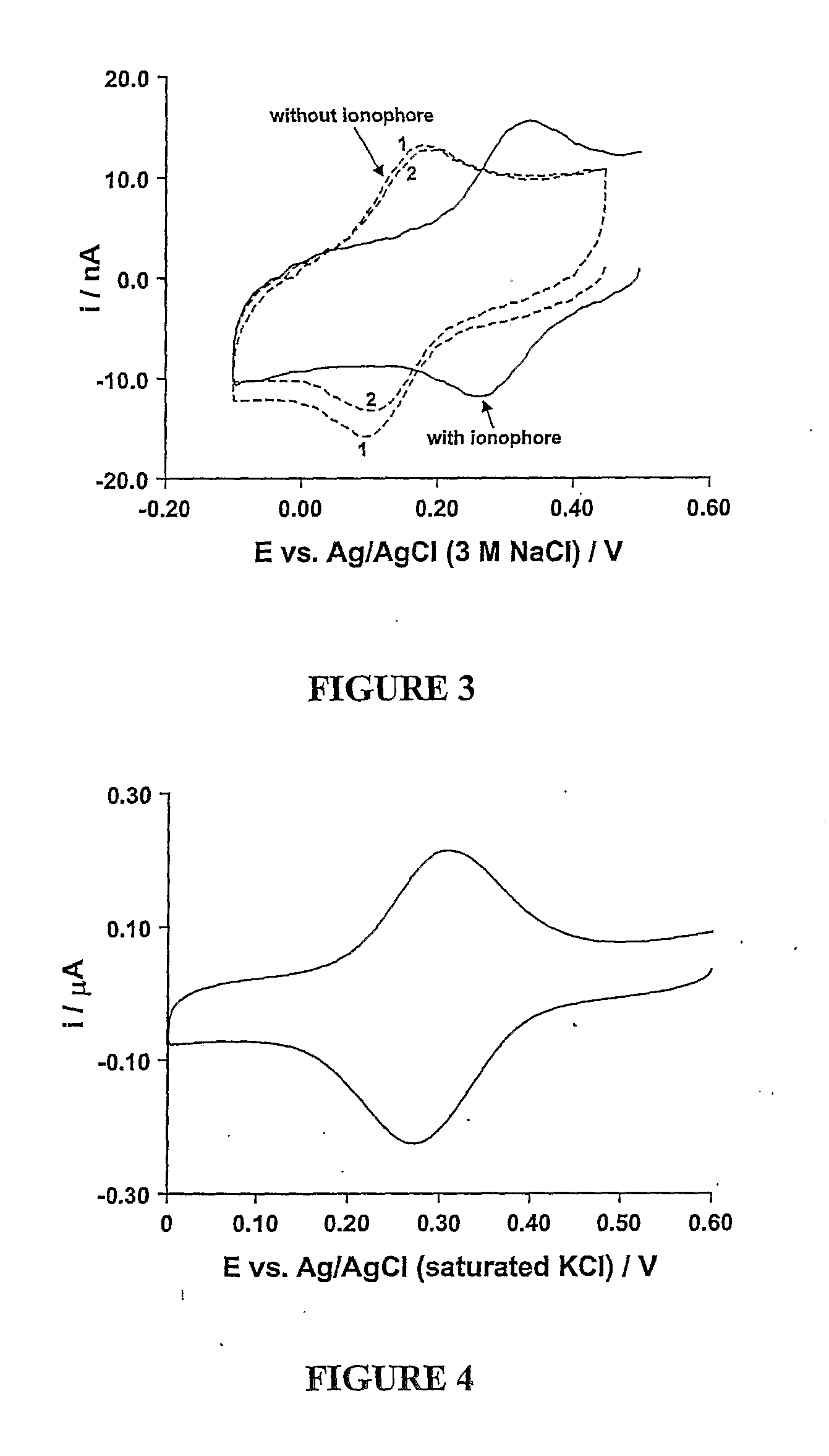
[0073] A sensor was produced in the same manner as described in Example 1, but replacing the NPOE plasticizer with the ionic liquid aph4.cph12 and eliminating the ionic salt (TBATPB). A measurement was carried out using a 0.1 mol dm−3 solution of KCl as the fluid in the same manner as is described in Example 2. The resulting voltammogram is depicted in FIG. 3. The solid line indicates the result for the above described sensor, whilst the dotted lines depict the result for a sensor which varied from the above only in that an ionophore was not used. In the absence of ionophore, the transfer of K+ into the membrane is less favourable resulting in movement of the oxidation and reduction peaks and decreasing peak current with cycle number due to redox active species transferring into the aqueous phase.


PUM

PropertyMeasurementUnit
volumesaaaaaaaaaa
diameteraaaaaaaaaa
volumeaaaaaaaaaa

Abstract

A method for the quantitative determination of an ion in a fluid which comprises subjecting the fluid to voltammetry using a sensing electrode which comprises an electrically conducting support having a surface which is coated with a support matrix, the support matrix containing an electroactive species capable of being oxidised or reduced to form a charged species, and an ionophore.

Description

FIELD OF THE INVENTION [0001] The present invention relates to a method of quantitatively and selectively measuring ionic materials in fluids. The invention also relates to a device and an electrode for carrying out such measurements. BACKGROUND TO THE INVENTION [0002] The most common method of quantitative and selective detection of ions has been by using ionophore based ion-selective electrodes (ISEs). The ionophore based ISE has been developed into a routine analytical technique in a wide range of fields since the 1960s. In this type of ISE, ionophore is dissolved in a polymer supported water immiscible organic solvent or plasticizer together with some other additives, such as organic supporting electrolyte (e.g. tetraheptylammonium(4-chlorophenyl) borate). Good selectivity is achieved mainly due to the specific ion binding process of ionophore. Under ideal conditions, the potential difference between the ISE and reference electrode, ΔE, is mainly varied by the Donnan potential a...

Claims


Application Information

Patent Timeline
Patent Type & Authority Applications(United States)
IPC IPC(8): G01N27/333G01N27/30G01N27/49
CPCG01N27/48G01N27/3335
Inventor ZHANG, JIEBOND, ALAN MAXWELLHARRIS, ALEXANDER RICHARD
Owner ROCHE DIAGNOSTICS OPERATIONS INC
Why Eureka
Try Eureka