Light source unit, phase type optical element, and laser beam scanning device

Active Publication Date: 2008-01-24
RICOH KK
View PDF10 Cites 43 Cited by
  • Summary
  • Abstract
  • Description
  • Claims
  • Application Information

AI Technical Summary

Benefits of technology

[0051]According to an embodiment of the present invention, in a phase type optical element in a light source unit, since the phase type optical element has a phase distribution in which a first ratio is greater than a second ratio, the beam spot diameter of laser beams at a focal position of an optical condensing element is restrained from been enlarged. That is, the main lobe laser beams are restrained from being enlarged. Therefore, a depth margin can be widened at high light use efficiency without enlarging the beam spot diameter.
[0052]According to an embodiment of the present invention, in a phase type optical element, a diffraction optical element can be added to a depth widening function without increasing cost, which diffraction optical element is used to reduce displacement of an image forming position caused by an environmental change, to be compatible for plural wavelengths (for example, blue, red, and colors other than the blue and red) by a single objective lens, and to correct aberration; the phase type optical element can further stabilize the beam spot diameter. In addition, since the phase type optical element can widen the depth margin, a change of the beam spot diameter caused by a temperature change can be decreased; further, a change of the beam spot diameter caused by deformation and vibration of an apparatus using the phase type optical element can be decreased. In addition, since the phase type optical element

Problems solved by technology

However, the performance of the optical device is degraded.
When it is desired that an exact Bessel beam is generated, an infinitely wide plane wave is required; consequently, it is impossible to generate the exact Bessel beam.
However, when the ring-shaped slit is used, the center part having a large amount of the laser beams is blocked and the light use efficiency becomes very low.
However, since the Bessel beams are generated near optical components, suitable arrangement of the optical components is difficult.
Consequently, the number of lenses is increased and the optical system becomes large and the cost is increased.
Therefore, an error may occur in the manufacturing process of the optical device and a malfunction of the optical device caused by an environmental change may occur. FIG. 30 is a diagram showing a part of the optical system which generates the Bessel beams by using the axicon prism.
In addition, when the Bessel beams are used in an optical device, since the side lobe laser beams are noise laser beams, too large side lobe laser beams may degrade output image quality of the optical device.
Especially, the high-order side lobe laser beams are generated at positions apart from the optical axis and are spatially separated from the main lobe laser beams (highest intensity laser beams); therefore, the noise may affect the output image quality of

Method used


Image

  • Light source unit, phase type optical element, and laser beam scanning device
  • Light source unit, phase type optical element, and laser beam scanning device
  • Light source unit, phase type optical element, and laser beam scanning device

Examples


first embodiment

[0133][Light Source Unit]

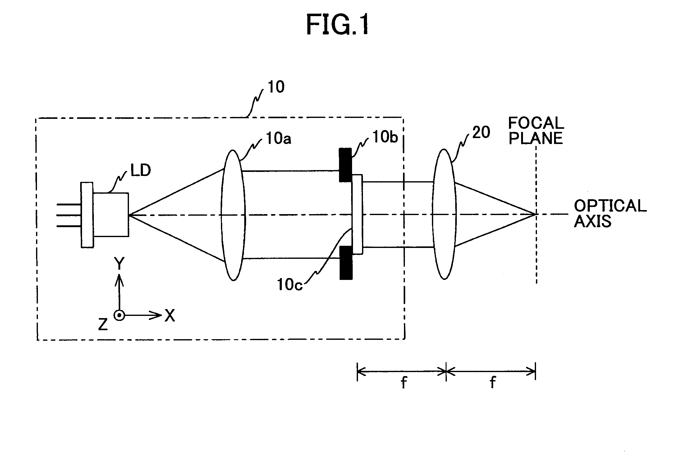
[0134]First, referring to FIGS. 1 through 23, a light source unit according to a first embodiment of the present invention is described. FIG. 1 is a schematic diagram showing a light source unit 10 according to the first embodiment of the present invention. In FIG. 1, in addition to the light source unit 10, a condenser lens 20, a focal plane, and an optical axis are shown.

[0135]As shown in FIG. 1, the light source unit 10 includes a semiconductor laser LD (laser diode) which is a light source, a coupling lens 10a, an aperture 10b, and a phase type optical element 10c. In the present embodiment, the optical axis direction of the coupling lens 10c is the X axis direction, the direction orthogonal to the X direction is the Y direction, and the direction orthogonal to the X and Y directions is the Z direction.

[0136]The semiconductor laser LD emits laser beams in the +X direction. In this, the wavelength of the laser beam is, for example, 632.8 nm.

[0137]The coup...

second embodiment

[Second Embodiment]

[0259]Next, referring to the drawings, a second embodiment of the present invention is described.

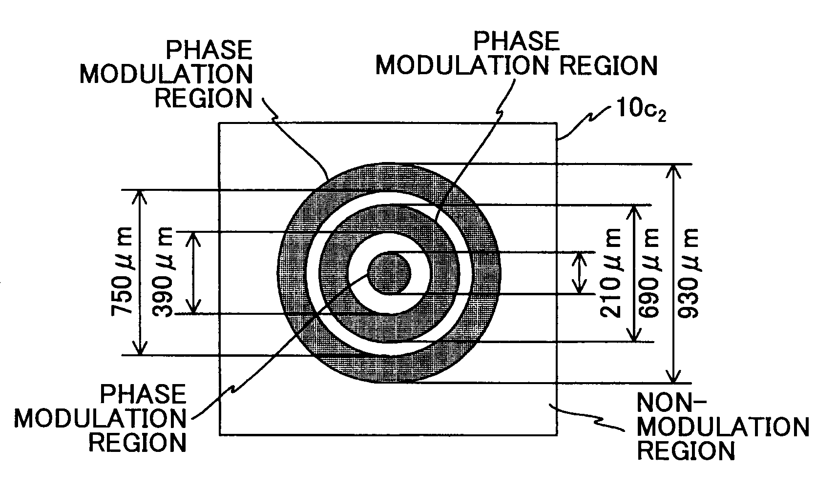
[0260]In the second embodiment, a reference number of an element is different from that in the first embodiment. For example, in the first embodiment, the phase type optical element 10c is used; however, in the second embodiment, a phase type optical element 2 is used.

[0261]First, a method is described in which the depth margin is widened without making the beam spot diameter large.

[0262]When diffraction of laser beams is suitably controlled, the depth margin is widened without making the beam spot diameter large. That is, a diffraction optical element is used. The diffraction optical element controls a phase distribution of laser beams by using a concave-convex surface and a refractive index distribution of the diffraction optical element. In the second embodiment of the present invention, a phase type optical element is formed by unifying with the diffraction lens (t...

third embodiment

[Third Embodiment]

[0347]Next, referring to the drawings, a third embodiment of the present invention is described.

[0348]In the third embodiment, the reference number of an element is basically different from that in the first and the second embodiments. In some cases, the same reference number as that in the first and second embodiments is used in the third embodiment, and within the third embodiment, the same reference number is used for the same element. In addition, when a suffix is not attached to a reference number of an element, the reference number represents the set of elements.

[0349][Laser Beam Scanning Device]

[0350]Referring to FIGS. 44, 46 shown in the second embodiment, and FIG. 49, a laser beam scanning device is described. The structure of the laser beam scanning device shown in FIGS. 44 and 46 has been described before; therefore, the same description is omitted. FIG. 49 is a schematic diagram of a light source unit 250 shown in FIG. 44. However, the structure of the ...


PUM


Abstract

A light source unit is disclosed. The light source unit includes a phase type optical element which modulates a phase distribution of laser beams emitted from a light source. The phase type optical element has a phase distribution so that a first ratio of the peak intensity of side lobe laser beams to the peak intensity of main lobe laser beams in a beam intensity profile at a focal position of the laser beam condensing element is greater than a second ratio of the peak intensity of side lobe laser beams to the peak intensity of main lobe laser beams in the beam intensity profile at the focal position of the laser beam condensing element when it is assumed that the phase type optical element is not disposed.

Description

BACKGROUND OF THE INVENTION[0001]1. Field of the Invention[0002]The present invention generally relates to a light source unit which irradiates laser beams, a phase type optical element which is used in the light source unit, a laser beam scanning device which scans a surface to be scanned with the laser beams irradiated from the light source unit, an image forming apparatus using the laser beam scanning device, and an optical pickup device using the light source unit.[0003]2. Description of the Related Art[0004]Recently, a laser beam emitted from a laser such as a semiconductor laser has been widely used in optical devices such as an optical pickup device, a laser processing device, a laser beam scanning device which is used in, for example, a copying apparatus and a laser printer. In the optical devices, in many cases, the laser beams are used to form a beam spot and the size of the beam spot is preferably as small as possible.[0005]In addition, it is preferable that an error in t...

Claims


Application Information

Patent Timeline
IPC IPC(8): G11B7/00
CPCG02B5/1876G11B7/1398G11B7/1367G02B26/123
Inventor IMAI, SHIGEAKISUZUKI, SEIZO
Owner RICOH KK
Why Eureka
Try Eureka