
Chain for use in automobile engine

a technology for transmission chains and automobile engines, applied in driving chains, solid-state diffusion coatings, gearing, etc., to achieve the effects of reducing the surface roughness of pins, reducing the ten-point mean surface roughness (rz), and high hardness

Inactive Publication Date: 2008-01-24
TSUBAKIMOTO CHAIN CO
View PDF3 Cites 6 Cited by
  • Summary
  • Abstract
  • Description
  • Claims
  • Application Information

AI Technical Summary

Benefits of technology

[0013]The V2C-containing outermost layer of each of the pins, can be subjected to treatment, preferably barrel polishing, to reduce the surface roughness of the pin, that is, by reducing the ten point mean surface roughness (Rz) as measured using the Japanese Industrial Standard JIS 0601-1976.
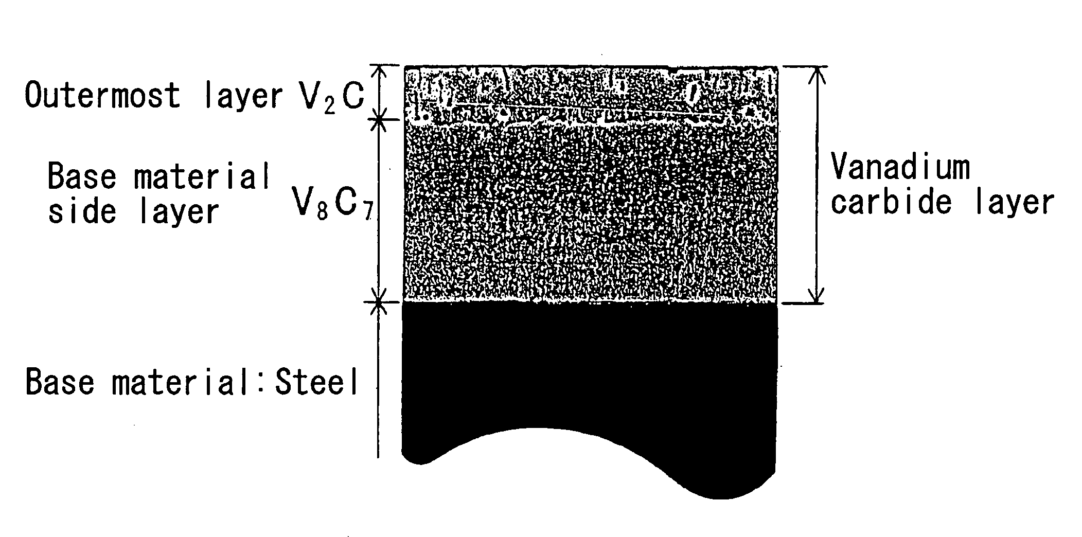
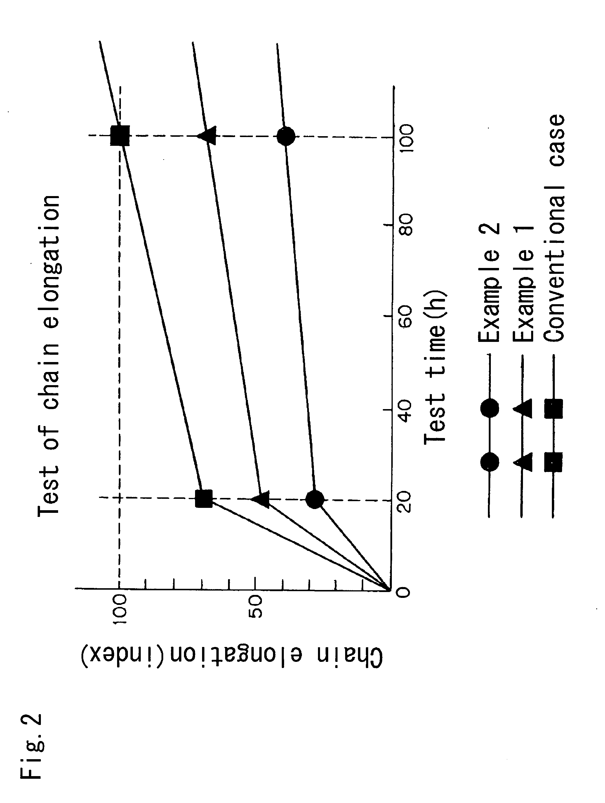
[0014]The V2C layer and the V8C7 layer exhibit different characteristics. The inner layer, which consists primarily of V8C7 on the base material of the pin, has a high hardness, i.e., a Vickers hardness (HV) of 2500 to 3000 or more. The outermost layer, which consists primarily of V2C is porous, and exhibits superior wear resistance, heat resistance and lubricity. Thus, even if the chain is used in an extremely deteriorated lubricating oil having a high degree of oxidation, a synergistic effect is achieved by the two layers. The second layer suppresses the attack on the first layer by deteriorated oil. Thus, abnormal wear elongation is suppressed, and a chain having excellent wear resistance, heat resistance and lubricity can be obtained for use in an automobile engine.
[0015]When the pin is subjected to treatment to reduce its surface roughness, the affinity of the pin for the inner surfaces of the pin holes in the inner link plates of a silent chain, or in the bushings of a roller chain or a rollerless bushing chain, is reduced. Furthermore, wear occurring during initial conformation of the pins and the pin holes is reduced. Thus, both initial wear and steady-state wear are reduced.
[0016]Various finishing processes are available for reducing the surface roughness of the pin. Among the options is “superfinishing,” which is a process used to finish inner and outer surfaces of a workpiece. The superfinishing process comprising using a spring to press a grindstone into contact with a wide surface area of a rolling workpiece, and imparting a minute, low-frequency, vibration in the direction of the axis of rotation of the rolling workpiece. Another option is chemical polishing, in which a workpiece is immersed in a processing solution to make the surface of the work smooth by a chemical reaction, thereby imparting brilliance to the work. Another option is electrolytic polishing, in which the workpiece is immersed in an electrolytic solution and passing an electric current between the workpiece, which is connected to the positive side of the electric current supply and becomes an anode, and another electrode which is immersed in the electrolytic solution and connected to the negative side of the electric current supply so that it becomes a cathode. The surface of the workpiece is eluted into the electrolytic solution. The best option, however, is barrel polishing. When barrel polishing is used as the treatment to reduce the surface roughness of the pin, greater friction is generated between the pin being worked and the abrasive material used in the finishing process. Barrel polishing produces results superior to those produced by superfinishing, chemical polishing, and electrolytic polishing, and makes it possible to carry out finishing of a small part such as a pin efficiently.
[0017]When the inner vanadium carbide layer on the pin, i.e., the layer containing V8C7, is thicker than an outer vanadium carbide layer, containing V2C, good wear resistance can be achieved while the affinity of the pin for wall of the pin hole is reduced. Thus, the shock resistance of the chain is improved, and abrasion loss of the inner surface of the pin hole can be suppressed.
[0018]The invention provide, for use in an automobile engine, a silent chain which exhibits excellent endurance, wear resistance and shock resistance. In addition, wear due to adhesion is suppressed, and therefore, the chain flexes and slides smoothly over a long period of time. Because the endurance of the chain is improved, the invention is also environmentally beneficial in that it can effectively extend the lifetime of the lubricating oil used with the chain.

Problems solved by technology

Thus, even if the chain is used in an extremely deteriorated lubricating oil having a high degree of oxidation, a synergistic effect is achieved by the two layers.

Method used


Image

  • Chain for use in automobile engine
  • Chain for use in automobile engine
  • Chain for use in automobile engine

Examples


Embodiment Construction

[0022]Although the invention will be described with reference to a silent chain, it should be understood that similar effects can be achieved in a roller chain and also in a rollerless bushing chain. In the case of a silent chain, the connecting pins are in sliding contact with the inner walls of the pin holes in the link plates of the chain. In the case of a roller chain or a rollerless bushing chain, the connecting pins are in sliding contact with the inner walls of the bushings. In all of these kinds of transmission chains, the invention can prevent deterioration due to sliding contact between the connecting pins and their opposed surfaces, especially in a deteriorated lubricating oil environment.

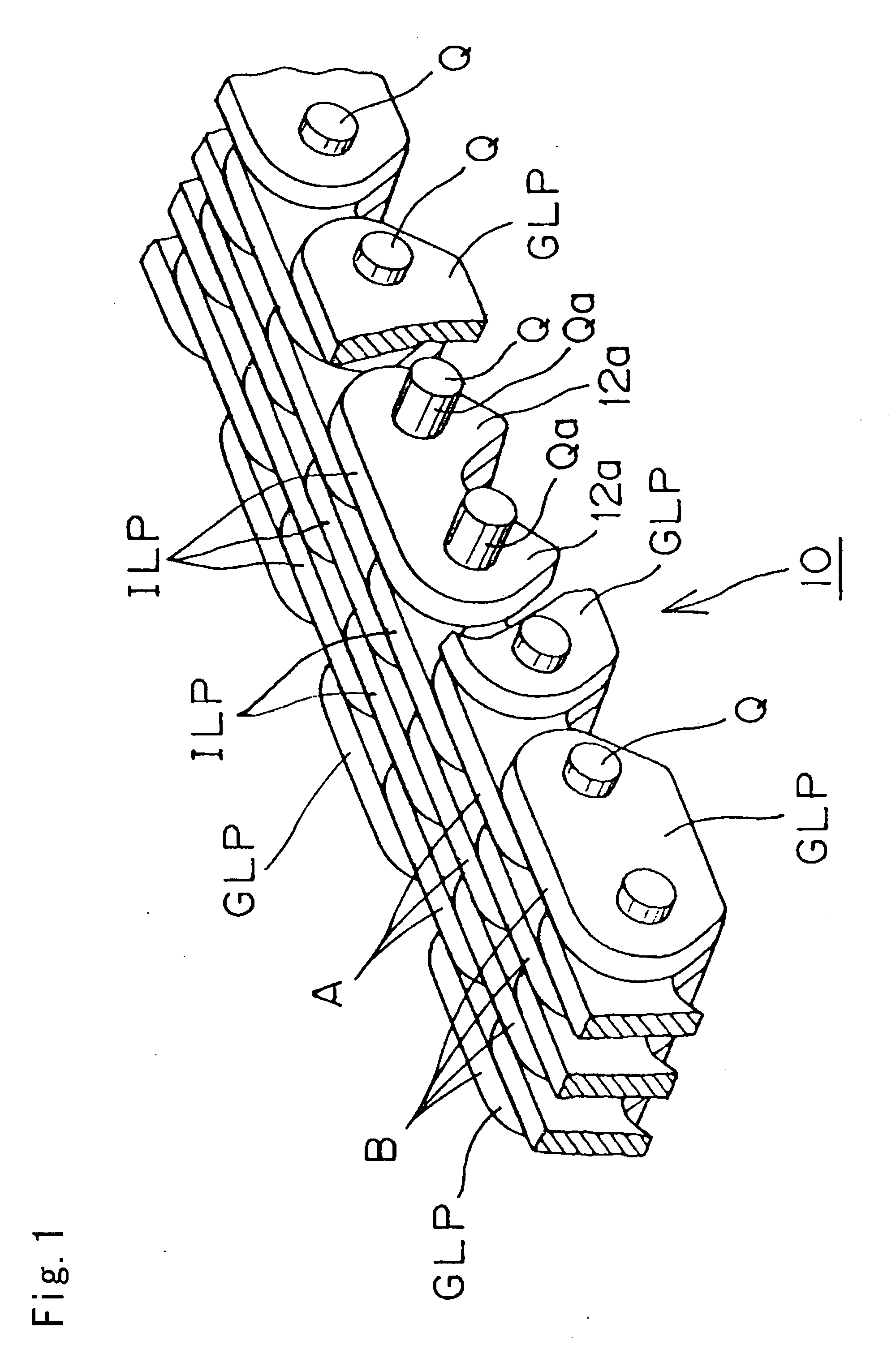
[0023]In FIG. 1, two guide link plates GLP are partly cut away to show a link plate having a pair of teeth 12a. The silent chain 10 is an endless chain formed by interleaved rows of link plates interconnected by pins Q. Each row comprises a plurality of inner link plates ILP, and every s...


PUM

PropertyMeasurementUnit
Fractionaaaaaaaaaa
Surface roughnessaaaaaaaaaa

Abstract

In a silent chain for an automobile engine timing drive, the pins which interconnect the link plates of the chain have a vanadium carbide layer formed on their surfaces by diffusion penetration. The vanadium carbide layer is composed of two parts: an inner part, on the steel base material of the pin, being a V8C7 layer, and an outermost part being a V2C layer.

Description

CROSS-REFERENCE TO RELATED APPLICATION[0001]This application claims priority on the basis of Japanese patent application 2006-195679, filed Jul. 18, 2006. The disclosure of Japanese application 2006-195679 is hereby incorporated by reference.FIELD OF THE INVENTION[0002]This invention relates to power transmitting chains for use in automobile engines, and to improvements particularly useful in timing chains, that is, chains used to deliver rotating power from an engine crankshaft to one or more valve-operating camshafts.BACKGROUND OF THE INVENTION[0003]Metal roller chains, and rollerless chains known as bushing chains, have come into increasing use as power transmitting media for automobile engines, and have displaced toothed belts and V-belts because of the demand for reliable high speed operation, greater endurance, and increased capacity to withstand mechanical loads, and also because roller chains and bushing chains require less maintenance, and afford greater freedom in the desi...

Claims


Application Information

Patent Timeline
IPC IPC(8): F16H7/06C23C10/36
CPCF16G13/04
Inventor NAGAO, KENICHI
Owner TSUBAKIMOTO CHAIN CO
Learn More