

Microphone amplifier
a technology of amplifier and microphone, applied in the direction of low frequency amplifier, electrical transducer, gain control, etc., can solve the problems of reduced sensitivity of condenser microphone and increased floor nois
- Summary
- Abstract
- Description
- Claims
- Application Information
AI Technical Summary
Benefits of technology
Problems solved by technology
Method used
Image

Examples
Embodiment Construction
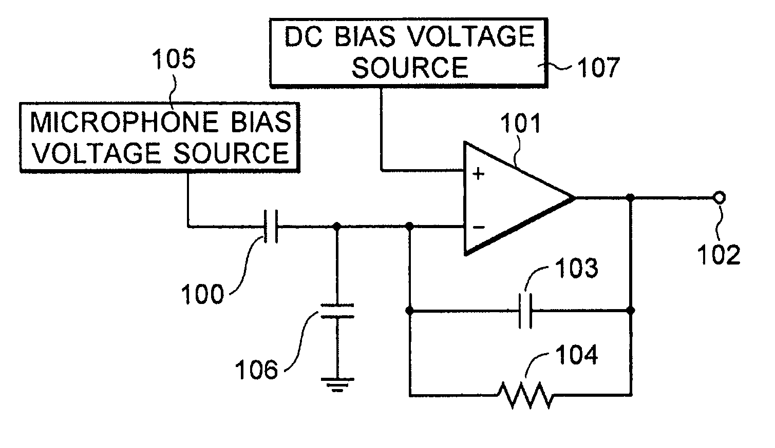
[0016] An embodiment of this invention is described in detail, referring to FIG. 1. FIG. 1 shows a microphone amplifier of a condenser microphone according to the embodiment.
[0017] The microphone amplifier shown in FIG. 1 has a condenser microphone 100 that converts a sound into a voltage signal, an operational amplifier 101 having an inverting input terminal (−) to which the voltage signal from the condenser microphone 100 is applied and a non-inverting input terminal (+) to which a direct current bias voltage is applied, a feedback capacitor 103 connected between the inverting input terminal (−) and an output terminal 102 of the operational amplifier 101, a feedback resistor 104 connected between the inverting input terminal (−) and the output terminal 102 of the operational amplifier 101, and a microphone bias voltage source 105 that provides the condenser microphone 100 with a direct current bias voltage.
[0018] A parasitic capacitance due to a pad, a gate capacitance of an ini...
PUM
 Abstract
Description
Claims
Application Information