RFID antenna system

a technology of rfid antennas and antenna earthings, which is applied in the direction of antenna earthings, substantially flat resonant elements, and resonant antennas, etc., can solve the problems of limited transmission distances available with conventional rfid systems, limiting their use in an automated factory setting, indoor wireless environment, and/or low reliability of systems

Inactive Publication Date: 2008-02-07
MOJIX
View PDF22 Cites 94 Cited by
  • Summary
  • Abstract
  • Description
  • Claims
  • Application Information

AI Technical Summary

Benefits of technology

[0030] The dielectric may be air. A multilayer printed circuit board may be included having the antenna feed network on a first layer and a ground plane on a second layer, wherein the patch element is supported about the ground plane on the second layer by standoffs so that the space between the ground layer and the patch element serves as the dielectric, and wherein each of the pair of metallic connection elements are bushings having a pin soldered at one end to the antenna feed network, the bushings screwed to the patch element at an other end. Each side of the square metallic patch may have a length and include a slot having a first width, a first end in the center of each such edge, a second end towards the center of the patch and an opening in the patch at each second end of each slot wider than the first width to increase the effective electrical wavelength of the antenna array element beyond the length of the edge.

Problems solved by technology

The limited transmission distances available with conventional RFID systems limits their use in an automated factory setting, and / or in an indoor wireless environment.
Even within in the designed range of operation, such systems often have low reliability due to interferences and collisions.
In addition, bandwidth usage may be high because the base station computer must communicate with and process information from every radio tag within its operational range.
The lack of available bandwidth limits the ability of a base station interacting with more than one radio tag at any given time.

Method used


Image

  • RFID antenna system
  • RFID antenna system
  • RFID antenna system

Examples


Embodiment Construction

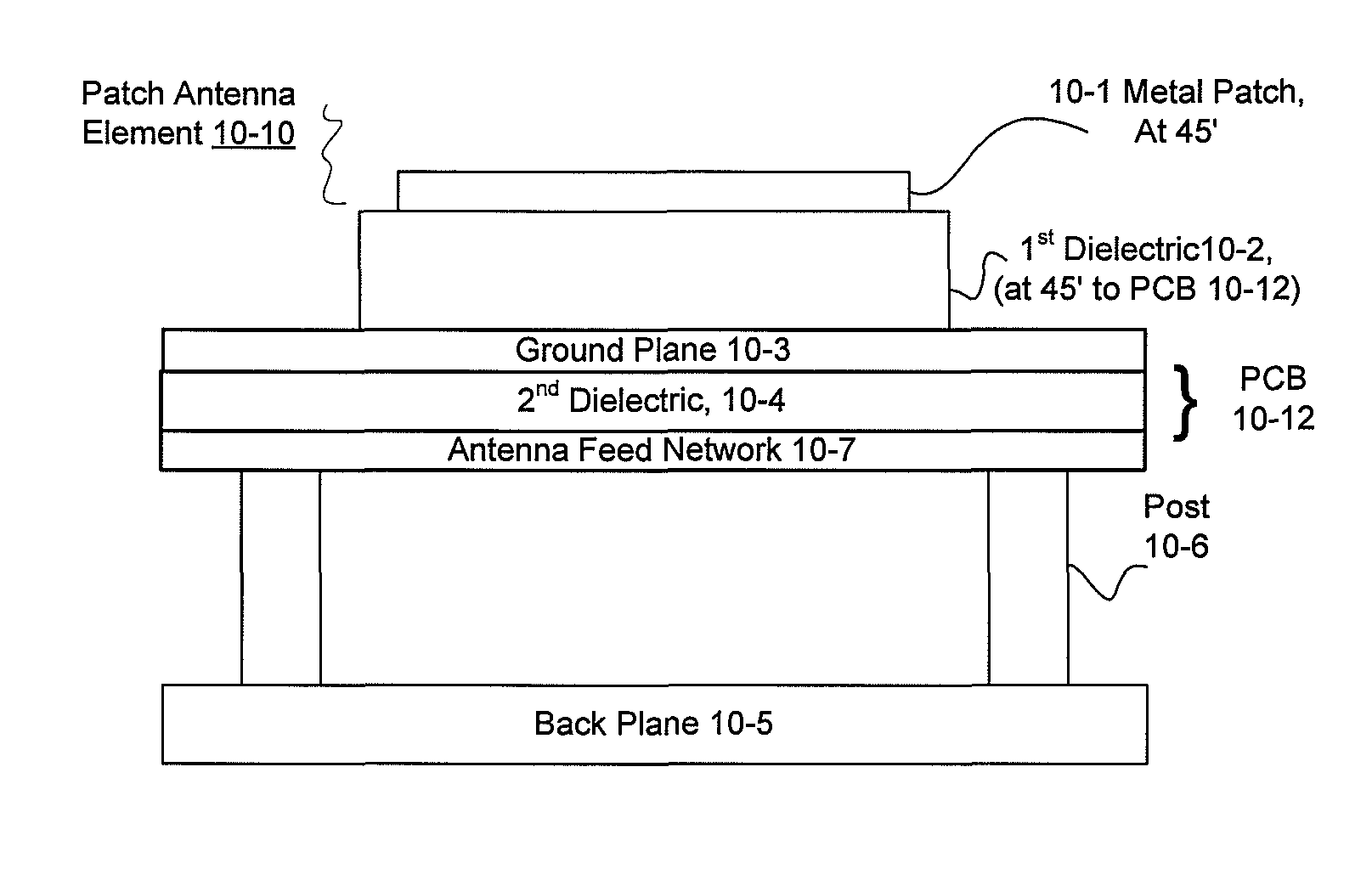
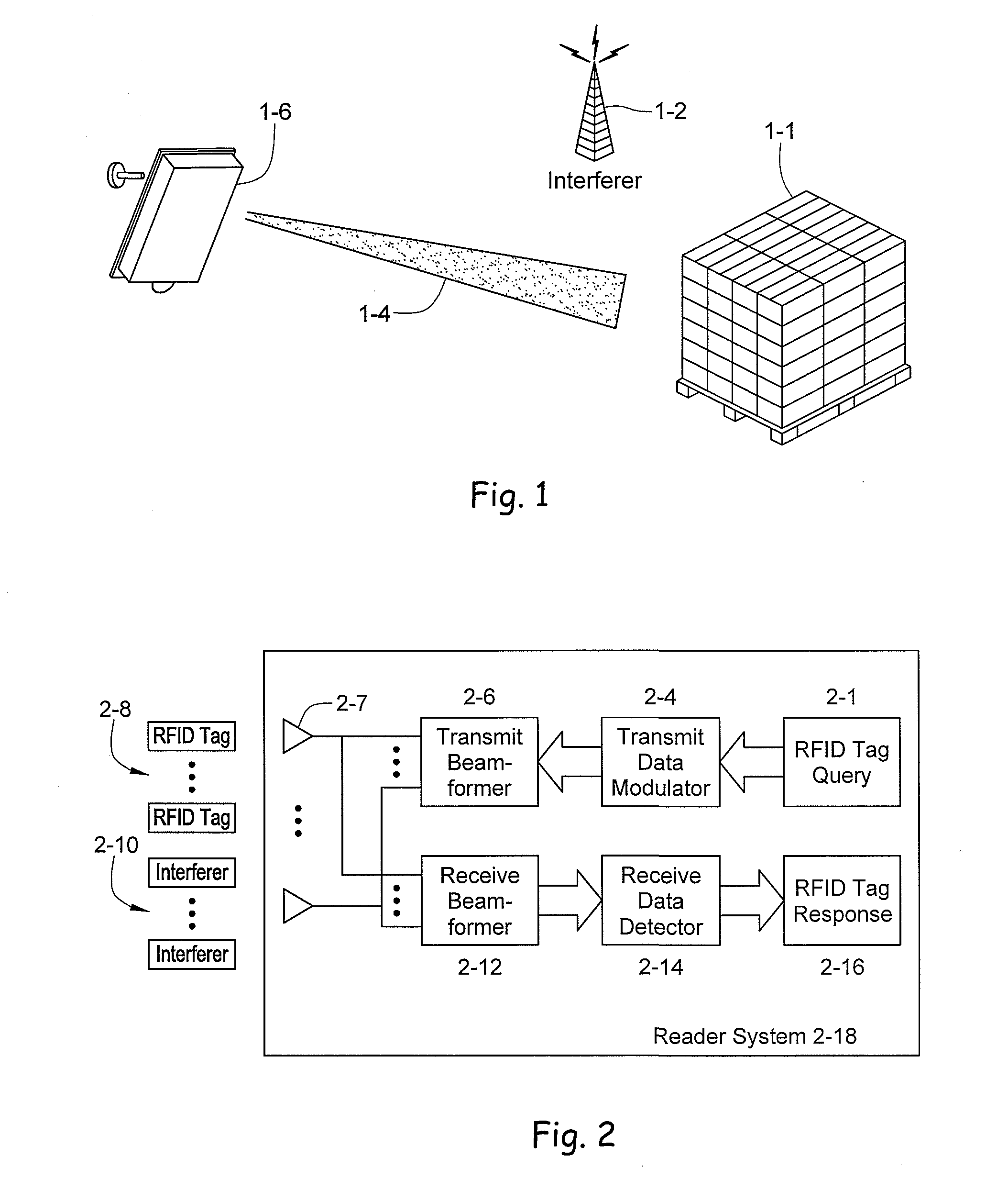
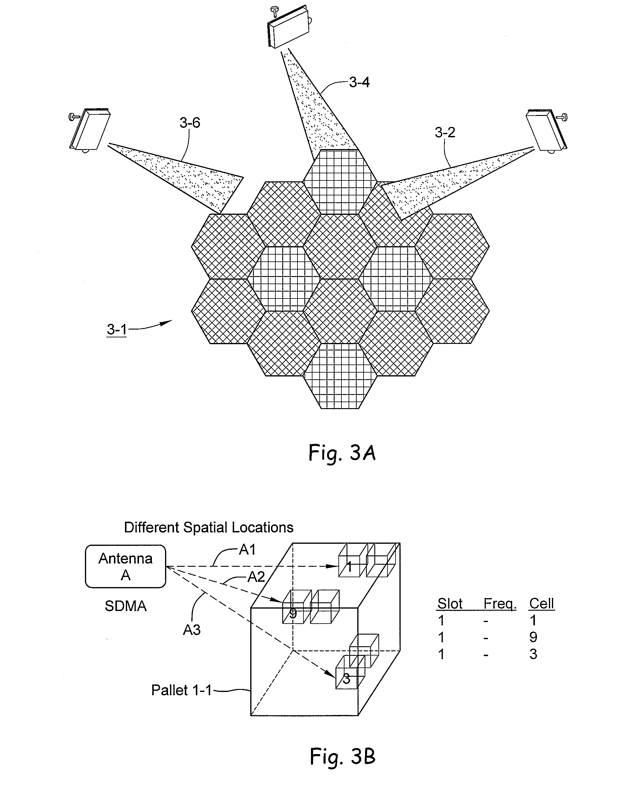
[0054] A radio frequency identification system reader is disclosed employing an antenna array. In the forward channel, that is the transmission path between the reader and the tag, the transmit antenna array may be distributed across several physical arrays. In the case of a distributed transmit antenna, the receive antenna array may capture the impinging energy from the tag signal excited by the antenna elements of a distributed array. This approach may use spatial multiplexing to provide substantial bandwidth utilization improvements over single antenna systems. The antenna array may support multiple frequency bands. An exemplar array element design includes an aperture-coupled feed tiled patch antenna. The tiled construction includes a matrix of identical elements in a two-dimensional plane. A low-noise amplifier (LNA) may be embedded in the antenna element itself to enhance the overall performance of the system.

[0055] For cases in which a transmit array antenna is used, beam fo...


PUM


Abstract

A multi-protocol, multi-band array antenna system may be used in Radio Frequency Identification (RFID) system reader and sensory networks. The antenna array may include array elements with an integrated low noise amplifier. The system may employ digital beam forming techniques for transmission and steering of a beam to a specific sensor tag or group of tags in an cell. The receive beam forming network is optimized for detecting signals from each sensor tag. Narrow and wideband interferences may be excised by an interference nulling algorithm. Space division multiplexing may be used by the antenna system to enhance system processing capacity.

Description

CROSS REFERENCE TO RELATED APPLICATIONS [0001] This application claims the benefit of the filing of provisional application Ser. No. 60 / 807,064 filed Jul. 11, 2006.BACKGROUND OF THE INVENTION [0002] 1. Field of the Invention [0003] This application relates to antenna systems used with passive or active sensors and in particular relates to antenna array systems and protocols used in Radio Frequency Identification (RFID) system base station and sensory networks. [0004] 2. Background of the Invention [0005] An RFID system conventionally includes a set of stationary or mobile RFID tags located within a physical area readable by a base station reader. Each sensor may be passive or active, with or without battery. In conventional systems, the reader and the RFID tags are generally required to be in close proximity so that the tags can operate in close proximity to the reader antenna. The limited transmission distances available with conventional RFID systems limits their use in an automat...

Claims


Application Information

Patent Timeline
Patent Type & Authority Applications(United States)
IPC IPC(8): H01Q1/38H01Q1/50
CPCH01Q1/2216H01Q9/0407H01Q3/26H01Q1/2225
Inventor GEVARGIZ, JOHNMANTEGHI, MAJEID
Owner MOJIX
Why Eureka
Try Eureka