

Nitrogen Oxide Removal Catalyst System And Nitrogen Oxide Removal Method
a nitrogen oxide and catalyst technology, applied in metal/metal-oxide/metal-hydroxide catalysts, machines/engines, arsenic compounds, etc., can solve problems such as environmental problems, use of catalysts including harmful components, and suggested use problems, so as to reduce the generation of nitrogen oxides, effectively remove nitrogen oxides, and efficiently remove nitrogen oxides
- Summary
- Abstract
- Description
- Claims
- Application Information
AI Technical Summary
Benefits of technology
Problems solved by technology
Method used
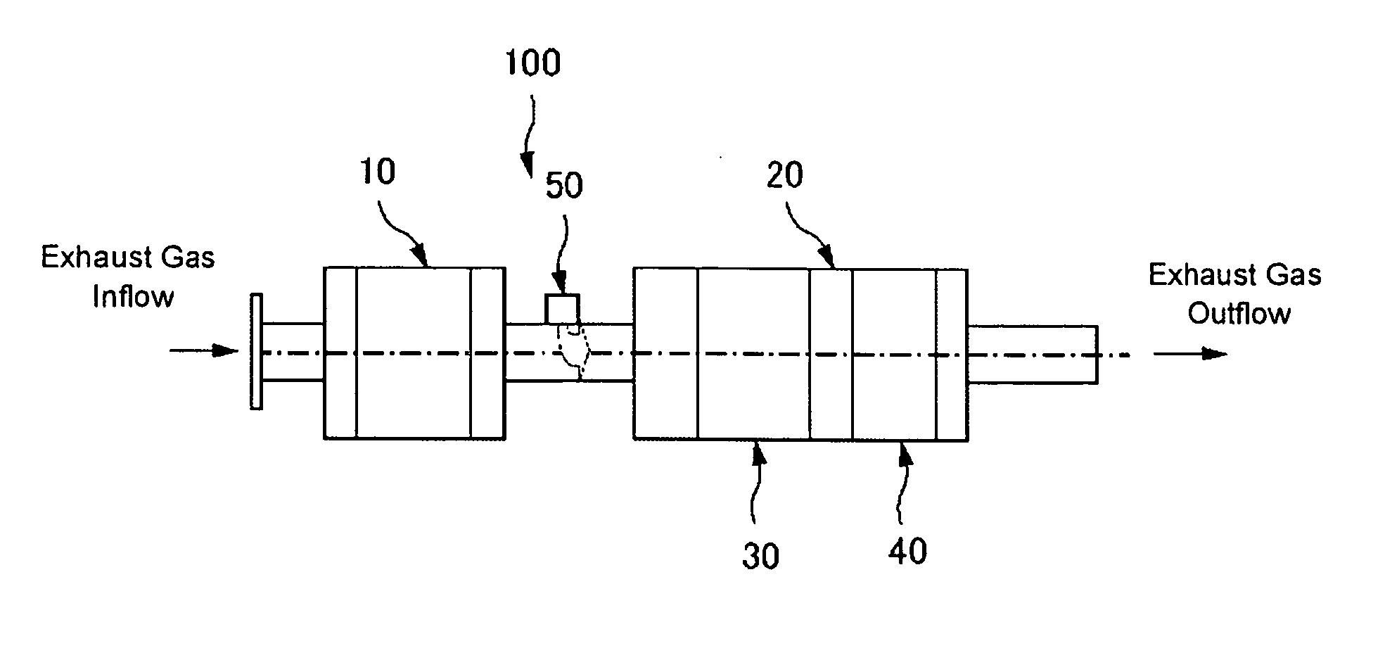
Image

Examples
example 1
4—Zr Based Catalyst>
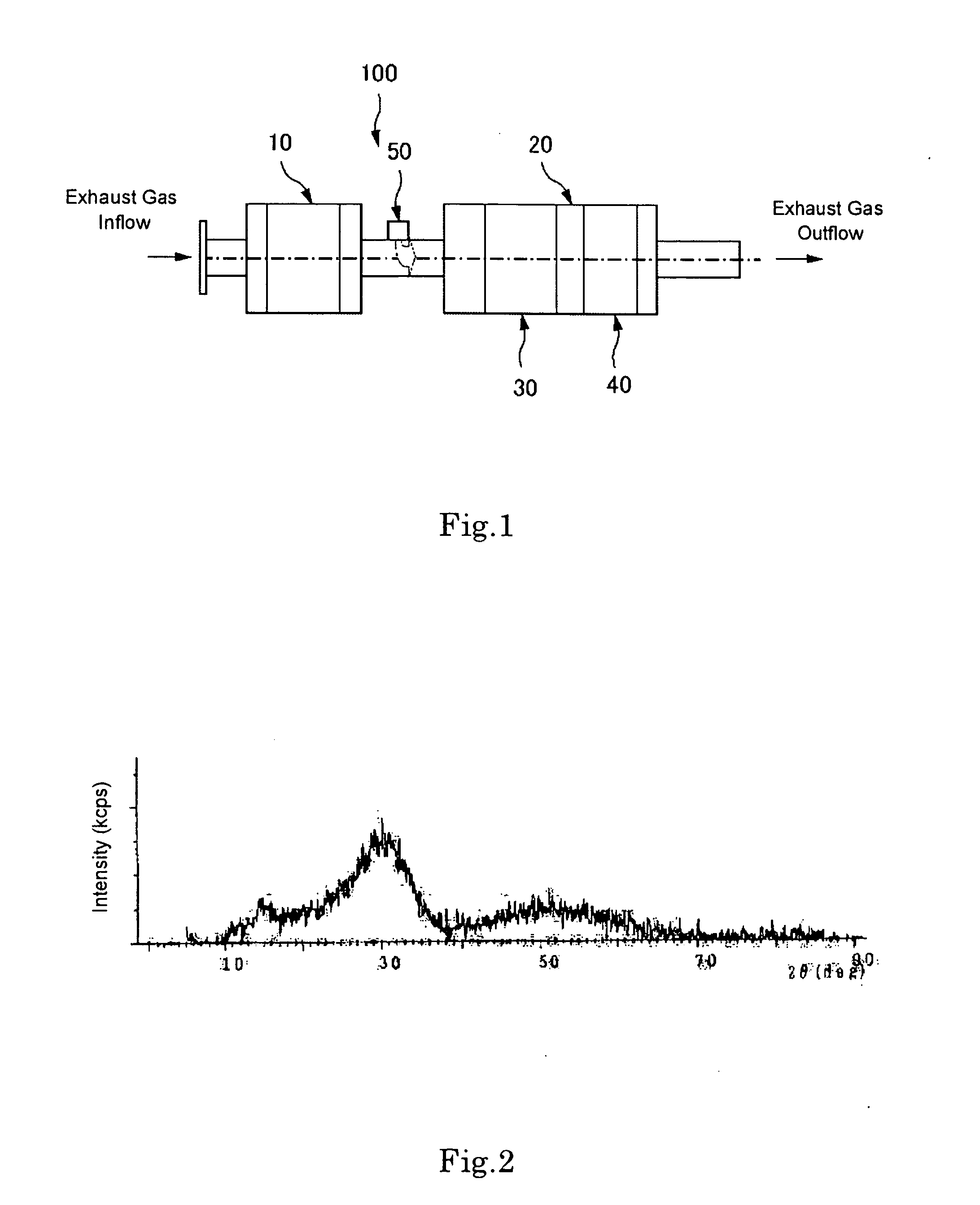
[0072] An aqueous mixture solution of 100 g of Zr salt (zirconium sulfate), 50 g of Ti salt (titanium chloride), and 50 g of Ce salt (cerium nitrate) dissolved in 1 L of water, was prepared, followed by addition of an alkali solution (ammonia water) for neutralization, and filtration. The solution was fired at 400° C. or higher and pulverized to obtain a powder. Thereafter, it was confirmed by X-ray diffractometry that this powder was a Ce—Ti—SO4—Zr based catalyst (see FIG. 2).
example 2
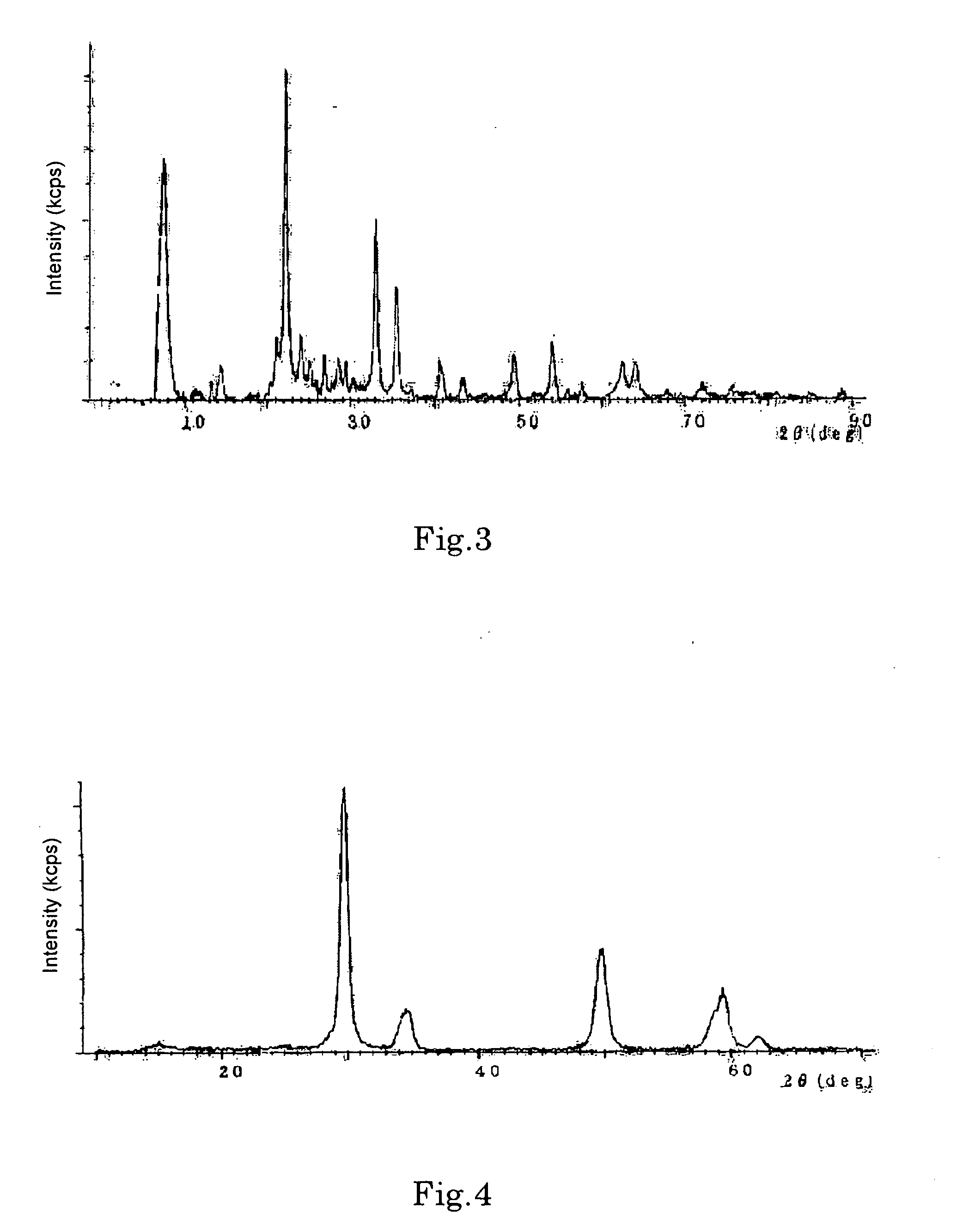
[0073] An aqueous solution of iron nitrate (made by dissolving 1,000 g of iron nitrate in 500 L of water) was gradually dropped onto 1,000 g of a porous oxide made of silica-alumina (molar composition ratio=40 / 1) while stirring. Powdery matter obtained was dried at 120° C. was fired at 450° C. for 2 hours, thereby obtaining a powder. Thereafter, it was confirmed that this powder was an Fe—Si—Al oxide based catalyst (see FIG. 3).
example 3
[0074] An aqueous mixture solution of 100 g of Zr salt (zirconium sulfate) and 50 g of Ce salt (cerium nitrate) dissolved in 1 L of water was prepared, followed by addition of an alkali solution (ammonia water) for neutralization, and filtration. 15 g of ammonium tungstate was impregnated in the solution, which was then fired at 400° C. or higher, and pulverized to obtain a powder. Thereafter, it was confirmed that this powder was a Ce—W—Zr oxide based catalyst (see FIG. 4).
PUM
| Property | Measurement | Unit |
|---|---|---|
| temperature | aaaaa | aaaaa |
| temperature | aaaaa | aaaaa |
| temperature | aaaaa | aaaaa |
Abstract
Description
Claims
Application Information