Multilayer Optical Disc and Method and Apparatus For Making Same

a multi-layer, optical disc technology, applied in the field of information storage devices, can solve the problems of low output of valid discs connected with a high degree of faultiness, all the prior systems used to be very complicated, and the chance of further breaking or deforming the data layer, and achieve the effect of high recording density

Inactive Publication Date: 2008-02-14
HD2
View PDF5 Cites 6 Cited by
  • Summary
  • Abstract
  • Description
  • Claims
  • Application Information

AI Technical Summary

Benefits of technology

[0027] This invention offers a method and technology to manufacture multilayer reflective discs with high recording density in every layer. By the said method in the framework of every format of a single-/dual-layer disc its manufacture technology changes so that there appears a chance to increase the number of data layers to 3, 4 and more without changing their optical properties and, hence, double, triple, qu

Problems solved by technology

The U.S. Pat. Nos. 5,255,262; 5,202,875; 5,373,499; 5,446,723; 5,610,901; 5,666,344 assigned to the IBM relating to multilayer discs and respective drivers point out that all the prior systems used to be very complicated concerning reading the data from different layers by way of changing the lens' focus distance and removing cross talks from the neighboring layers and generation of the tracking signal.
The described method of manufacturing multilayer discs has a number of disadvantages, namely: a low output of valid discs connected with a high degree of faultiness while separating substrate 10 and transferring super thin (less than 50 μm) reflective layer 12 to the polycarbonate substrate, as well as a chance of further breaking or de

Method used


Image

  • Multilayer Optical Disc and Method and Apparatus For Making Same
  • Multilayer Optical Disc and Method and Apparatus For Making Same
  • Multilayer Optical Disc and Method and Apparatus For Making Same

Examples


example 1

[0050] The method of sputtering of DLC layer. 10 substrates with diameter 120 mm, thickness 0.54 mm made out of polycarbonate by injection molding and containing data in form of pits 0.12 μm deep, are placed on the low electrode of the Plasma Enhanced Chemical Vapor Deposition plant of condenser type, the temperature of which is maintained substantially 30° C. using built-in thermostat. Constant-temperature of electrode is needed for keeping substrates from possible fluctuations and overheating while they are being sputtered, which can cause heterogeneous sputtering. A layer of diamond-like carbon (DLC) is deposited on the substrate under the following conditions: reaction chamber gets vapors of acetonitril 1.5 lph, argon 1 lph, with vacuum 20 Pa, generator power is 500 Watt, frequency of generator work is 400 kHz. Time of sputtering is 6 min. In industrial setup the same effects and much faster are achieved by application of sputtering machines.

example 2

[0051] The method of producing plastic matrix. Polycarbonate substrate, made by injection molding, containing data in the form of micro-bumps of 0.12 μm high (made using metal stamper—“mother”) is placed on the lower thermo stated electrode of the reaction chamber in PEVCD plant, then it is being spattered by SiO2 under the following conditions: the reaction chamber gets vapors of hexamethyldisilazane 0.9 lph, argon 1.0 lph and oxygen 1.5 lph, with pressure in the chamber of 25 Pa and power 300 Watt for 1 hour the sputtering of SiO2 is being carried out. Then the substrate is processed by liquid dimethyldichloresilane for 15 sec, after that the surplus of the later is removed in spin dryer and surface is washed by isopropyl alcohol. The matrix is ready for further use.

example 3

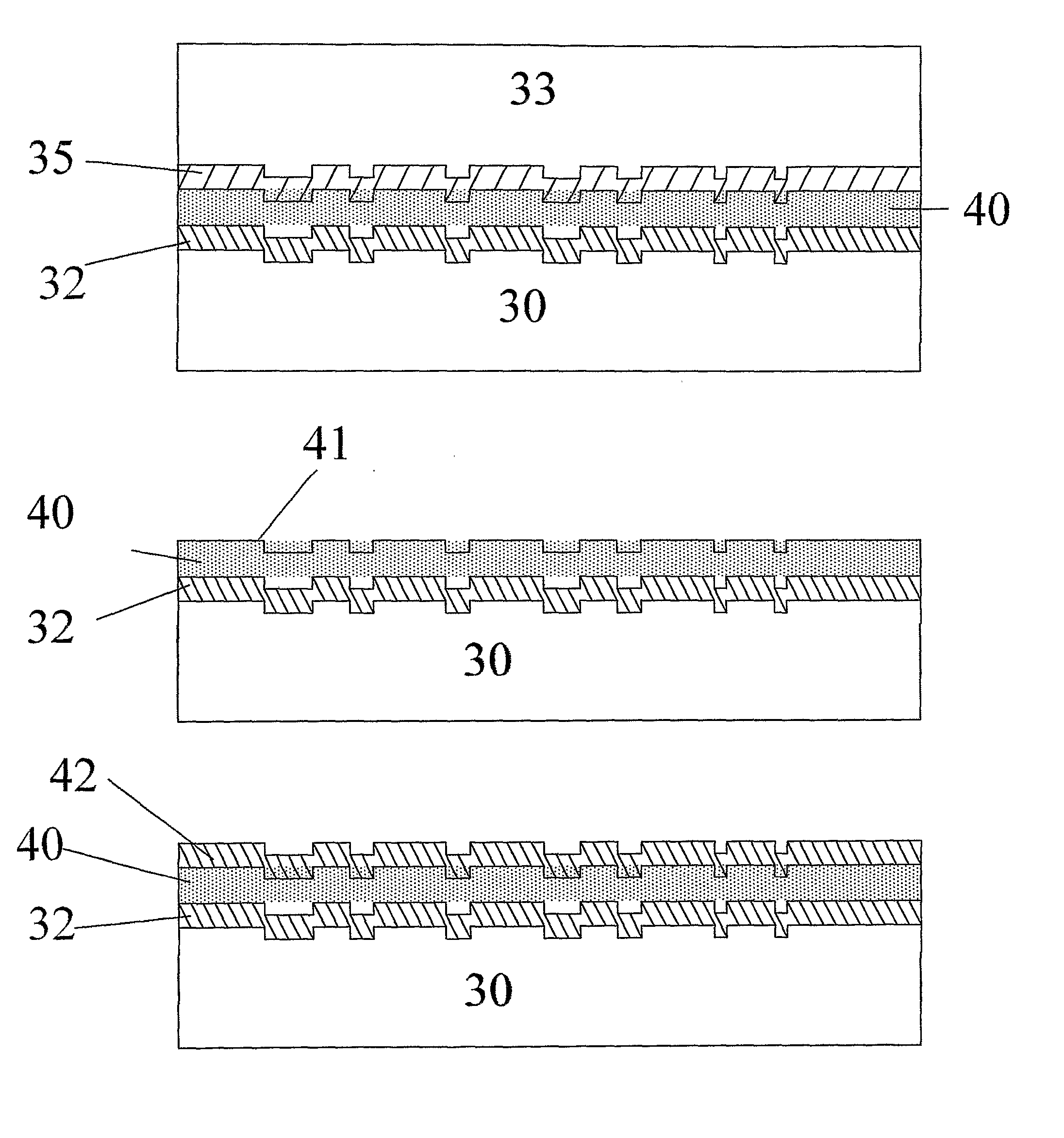
[0052] In the DVD-bonding machine the substrate with sputtered layer of DLC (the first data layer) similar to example 1 is stuck with plastic matrix with data of the second layer, produced according to example 2. The thickness of the glue layer is set to be 35-40 μm. 30 min after gluing the disk is divided into layers and the data relief from plastic matrix is carried to substrate with sputtered DLC, moreover plastic matrix is released, and then this matrix can be used again for producing the next disk. To remove electrostatic stress surfaces of substrate and matrix are washed by isopropyl alcohol. On the produced half-finished product of two-layer disk according to method sited in example 1, the second coating of DLC is sputtered and then it is stuck by DVD-bonding machine with the plastic matrix bearing information of the third layer. After separating the produced half-finished disk is washed by isopropyl alcohol and stuck with a blank polycarbonate substrate in DVD bonding machin...


PUM


Abstract

Multilayer Optical Disc and Method and Apparatus for making same are proposed The technology provides increasing the number of layers in reflective optical disks of any format. The technology allows producing of multilayer optical reflective discs of any format (CD, ROM, DVD ROM, Blue Ray, HD-DVD, DVD-R, DVD-RW, etc.) using existing CD/DVD production lines with reasonable upgrading.

Description

BACKGROUND OF THE INVENTION [0001] The invention relates to the field of information storage devices in general, and more particularly to multilayer optical discs and methods for making them including mass production. [0002] Optical systems of information storage provide for storing large volumes of various data as well as ways recording and reading thereof. [0003] HDTV, HD-video and high-speed Internet require inexpensive carriers with high recording capacity. The data recording density on one layer can be increased by way of using a shorter laser wave length and, respectively, smaller pit sizes. Another way is to increase the number of data layers, that is, to use a multilayer disc. Conventional DVDs have at most 2 layers on one side of the disk. [0004] Reading from optical information storage devices is usually carried out by a laser beam focused on one of the data layers with further registration of the reflected beam modulated with the pit-and-land pattern. [0005] The U.S. Pat....

Claims


Application Information

Patent Timeline
IPC IPC(8): B05D5/06G11B7/257G11B7/258
CPCG11B7/24038G11B7/2533G11B7/2534G11B7/2535G11B7/266G11B7/257G11B7/258G11B7/263G11B7/256
Inventor LEVICH, EUGENEBINYUKOV, VLADIMIRMAGNITSKII, SERGEIMALAKHOV, DMITRY
Owner HD2
Why Eureka
Try Eureka