Electron Spectroscopy Analysis Method and Analytical Apparatus

a technology of electron spectroscopy and analysis method, applied in the direction of material analysis by measuring secondary emission, material analysis using wave/particle radiation, instruments, etc., can solve the problems of increasing cost, difficult to execute uniform etching, and inconvenient analysis methods for comparatively large probes, etc., to achieve the effect of restricting the cost increas

Inactive Publication Date: 2008-02-21
ULVAC PHI
View PDF9 Cites 17 Cited by
  • Summary
  • Abstract
  • Description
  • Claims
  • Application Information

AI Technical Summary

Benefits of technology

[0021]In accordance with the present invention, it is possible to uniformly apply an etching process to a surface of a sample to be analyzed to such a level that a damage on the surface of the sample to be analyzed is negligible even when a contaminant on the surface of the sample to be analyzed is removed, by irradiating a fullerene ion beam to the surface of the sample to be analyzed before irradiating a high-energy particle to the surface of the sample to be analyzed. Accordingly, it is possible to precisely analyze a composition, a chemical state and the like of the sample to be analyzed.
[0022]Furthermore, since an ion gun irradiating a fullerene ion beam is not large, as compared with an apparatus forming a cluster (an ion source), a large-scale equipment is not required, and it is possible to restrict a cost increase.

Problems solved by technology

Accordingly, in an analysis method which can employ a small probe, such as an Auger electron spectroscopy analysis, these analysis methods are generally used, however, these analysis methods are not suitable for an analysis method employing a comparatively large probe, such as a photoelectron spectroscopy analysis.
In the method of the patent document 3 mentioned above, since it is necessary to prepare a cluster by preparing high-pressure gas and utilizing a gas jet generated by a pressure difference from a vacuum chamber, a large-scale equipment is necessary for being used for a surface analysis requiring an ultra-high vacuum apparatus, and a cost is increased.
Furthermore, since speeds of one hundred or more clusters are different depending on the number of the clusters, a surface irregularity tends to be caused, for example, in a scanned range, and it is difficult to execute a uniform etching.
In the non-patent document 4 mentioned above, since a neutral particle is employed in place of an ion, a repeatability does not exist in an operation, and it is difficult to quantitatively estimate an etching amount.
Therefore, the large-scale equipment is required in the same manner as in the case of the cluster ion mentioned above, and the cost is also increased.

Method used


Image

  • Electron Spectroscopy Analysis Method and Analytical Apparatus
  • Electron Spectroscopy Analysis Method and Analytical Apparatus

Examples


embodiment 1

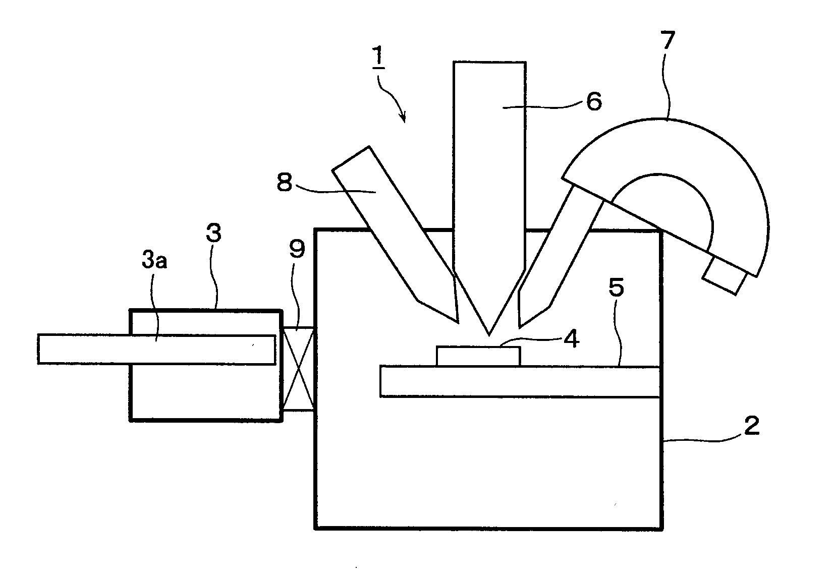
[0024]FIG. 1 is a skeleton schematic view showing an electron spectroscopy analytical apparatus in accordance with an embodiment 1 of the present invention. An electron spectroscopy analytical apparatus 1 in accordance with the present embodiment is provided with a vacuum chamber 2 to which a vacuum pump system (not shown) is connected, as shown in FIG. 1. And a sample stage 5 for arranging and fixing a sample (an analyzed object) 4 to be carried from an external portion by the carrier device 3 is provided within the vacuum chamber 2.

[0025]Furthermore, in an upper portion of the vacuum chamber 2, there are placed a high-energy particle irradiating unit 6 irradiating a high-energy particle (an X-ray in the present embodiment) to the sample 4 mounted on the sample stage 5, an electron energy analyzer 7 for analyzing an energy of electrons emitted from the surface of the sample 4 by the high-energy particle irradiated to the surface of the sample 4 from the high-energy particle irradia...

embodiment 2

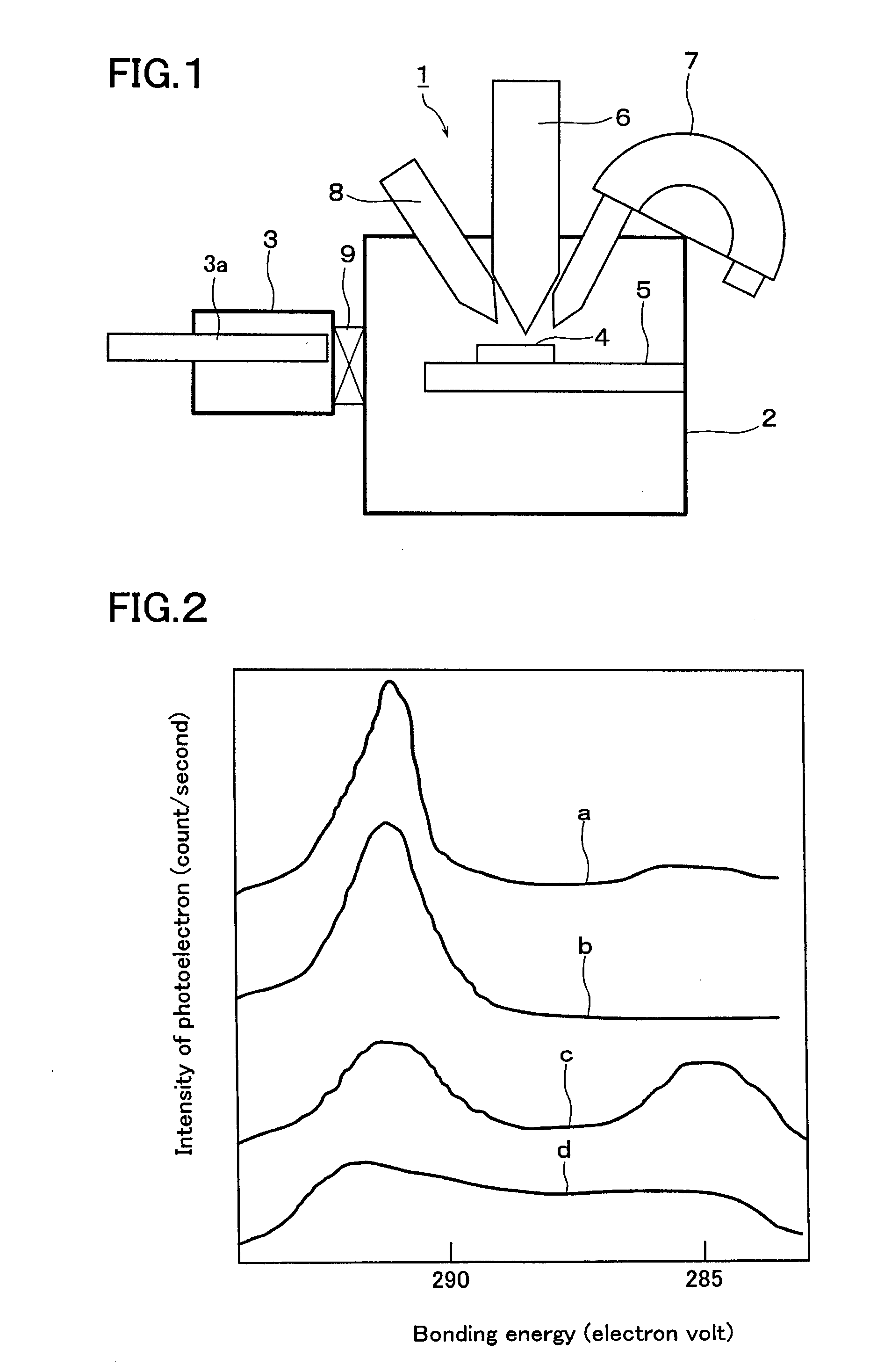
[0038]In the present embodiment, the X-ray photoelectron spectroscopy analysis of the polytetrafluoroethylene (PTFE) ((CF2)n) as the sample 4 is executed by using the electron spectroscopy analytical apparatus 1 in accordance with the embodiment 1 shown in FIG. 1. The structure of the electron spectroscopy analytical apparatus 1 is approximately the same as in the embodiment 1, and an overlapping description will not be repeated here.

[0039]A description will be given of an electron spectroscopy analysis method by an electron spectroscopy analytical apparatus 1 in accordance with an embodiment 2 of the present invention.

[0040]First, the sample 4 is mounted on the sample stage 5 within the vacuum chamber2 through the open gate valve 9 by driving the carrier arm 3a of the carrier device 3 in the same manner as in the embodiment 1. Thereafter, the inner side of the vacuum chamber 2 is evacuated by a connected vacuum pump system (not shown) so as to be regulated to a predetermined pressu...


PUM

PropertyMeasurementUnit
pressureaaaaaaaaaa
pressureaaaaaaaaaa
energyaaaaaaaaaa

Abstract

[Task] The invention enables uniformly etching a surface of a sample with an improved repeatability, and etching at a low cost without requiring any large-scale equipment.
[Means for Solving the Problem] In an electron spectroscopy analytical apparatus (1) for executing an analysis of a composition, a chemical state and the like of a surface of a sample (4) or in a depth direction thereof by irradiating an X-ray to the sample (4) from a high-energy particle irradiating unit (6) within a vacuum chamber (2) under a vacuum atmosphere, and detecting a kinetic energy of electrons emitted from the sample (4) by an electric energy analyzer (7) on the basis of a photoelectric effect, the surface of the sample (4) is ion-etched by irradiating a fullerene ion beam to the surface of the sample (4) from an ion gun (8) before irradiating the high-energy particle to the sample (4).

Description

TECHNICAL FIELD[0001]The present invention relates to an electron spectroscopy analysis method and analytical apparatus for executing a desired analysis with respect to a surface or a depth direction of a sample to be analyzed by irradiating a high-energy particle to the sample to be analyzed under a vacuum atmosphere and detecting a number and a kinetic energy of electrons emitted from the sample to be analyzed on the basis of a photoelectric effect.BACKGROUND ART[0002]The electron spectroscopy analytical apparatus is widely used in a correlation analysis of functional physical property, a quality control, a process analysis work and the like for improving a product performance, for example, with respect to various samples prepared in a developing process and a manufacturing step of the various samples. In particular, an X-ray photoelectron spectroscopy analytical apparatus employing a characteristic X-ray as the high-energy particle is widely used for analyzing contamination, a co...

Claims


Application Information

Patent Timeline
Patent Type & Authority Applications(United States)
IPC IPC(8): G01N23/227G01N1/34G01N23/22G01N23/225
CPCB82Y15/00G01N23/2252G01N23/2202B82Y30/00
Inventor SANADA, NORIAKIOHASHI, YOSHIHARUYAMAMOTO, AKIRAOIWA, RETSU
Owner ULVAC PHI
Why Eureka
Try Eureka