Field effect transistors (FETS) with inverted source/drain metallic contacts, and method of fabricating same

a field effect transistor and metal contact technology, applied in the field of improved field effect transistors, can solve the problems of continuous size reduction of semiconductor devices, achieve the effect of reducing the number of source/drain metal contacts, reducing the total contact layout area, and reducing the effect of effective contact area

Active Publication Date: 2008-02-21
INT BUSINESS MASCH CORP
View PDF36 Cites 6 Cited by
  • Summary
  • Abstract
  • Description
  • Claims
  • Application Information

AI Technical Summary

Benefits of technology

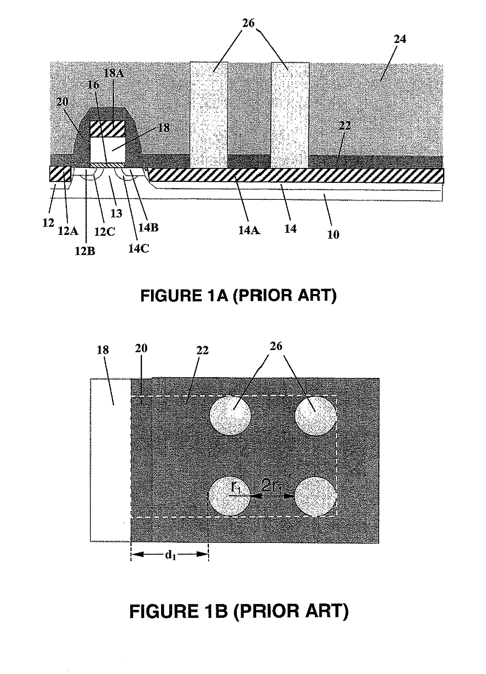
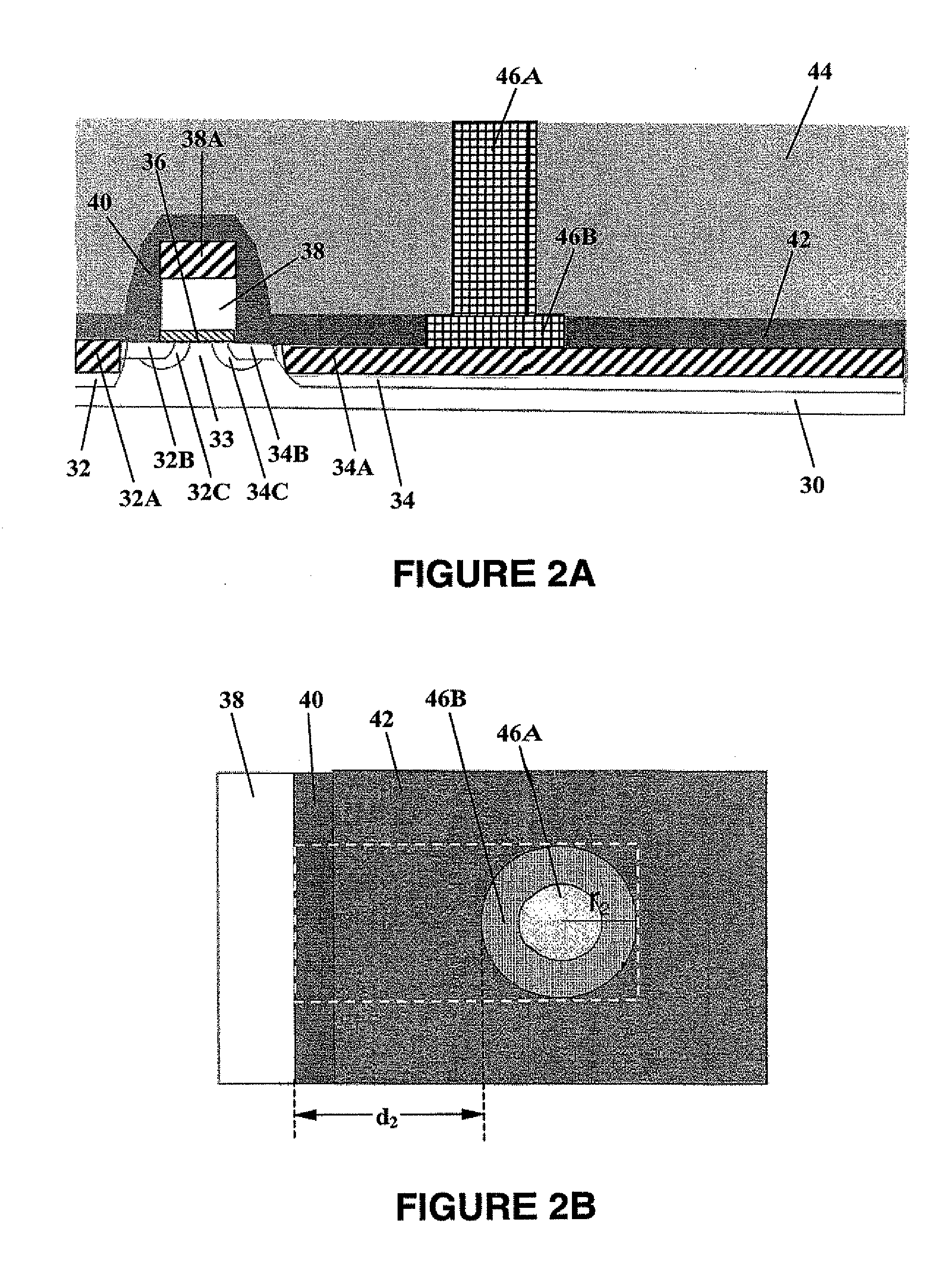
[0005] The present invention provides a solution to the contact spacing and parasitic capacitance issues by constructing an improved FET design. The improved FET design of the present invention is advantageously characterized by: (1) reduced number of source / drain (S / D) metal contacts, (2) reduced total contact layout area, (3) substantially the same effective contact area, (4) increased contact-to-gate distance, and (5) reduced gate-to-contact capacitance, in comparison with conventional FET designs. Further, the improved FET of the present invention is relatively easier to manufacture than the conventional FETs and can be fabricated at significantly increased product yield with reduced manufacturing costs.

Problems solved by technology

The demand for increased speed, in turn, has resulted in a continual size reduction of the semiconductor devices.
However, the aggressive scaling or size reduction of the FETs also raises various technical issues relating to contact spacing and parasitic capacitance, which need to be addressed in order to meet the requirements for both device performance and manufacturing yield.

Method used


Image

  • Field effect transistors (FETS) with inverted source/drain metallic contacts, and method of fabricating same
  • Field effect transistors (FETS) with inverted source/drain metallic contacts, and method of fabricating same
  • Field effect transistors (FETS) with inverted source/drain metallic contacts, and method of fabricating same

Examples


Embodiment Construction

[0027] In the following description, numerous specific details are set forth, such as particular structures, components, materials, dimensions, processing steps and techniques, in order to provide a thorough understanding of the present invention. However, it will be appreciated by one of ordinary skill in the art that the invention may be practiced without these specific details. In other instances, well-known structures or processing steps have not been described in detail in order to avoid obscuring the invention.

[0028] It will be understood that when an element as a layer, region or substrate is referred to as being “on” another element, it can be directly on the other element or intervening elements may also be present. In contrast, when an element is referred to as being “directly on” another element, there are no intervening elements present. It will also be understood that when an element is referred to as being “connected” or “coupled” to another element, it can be directl...


PUM

PropertyMeasurementUnit
areaaaaaaaaaaa
areaaaaaaaaaaa
distanceaaaaaaaaaa

Abstract

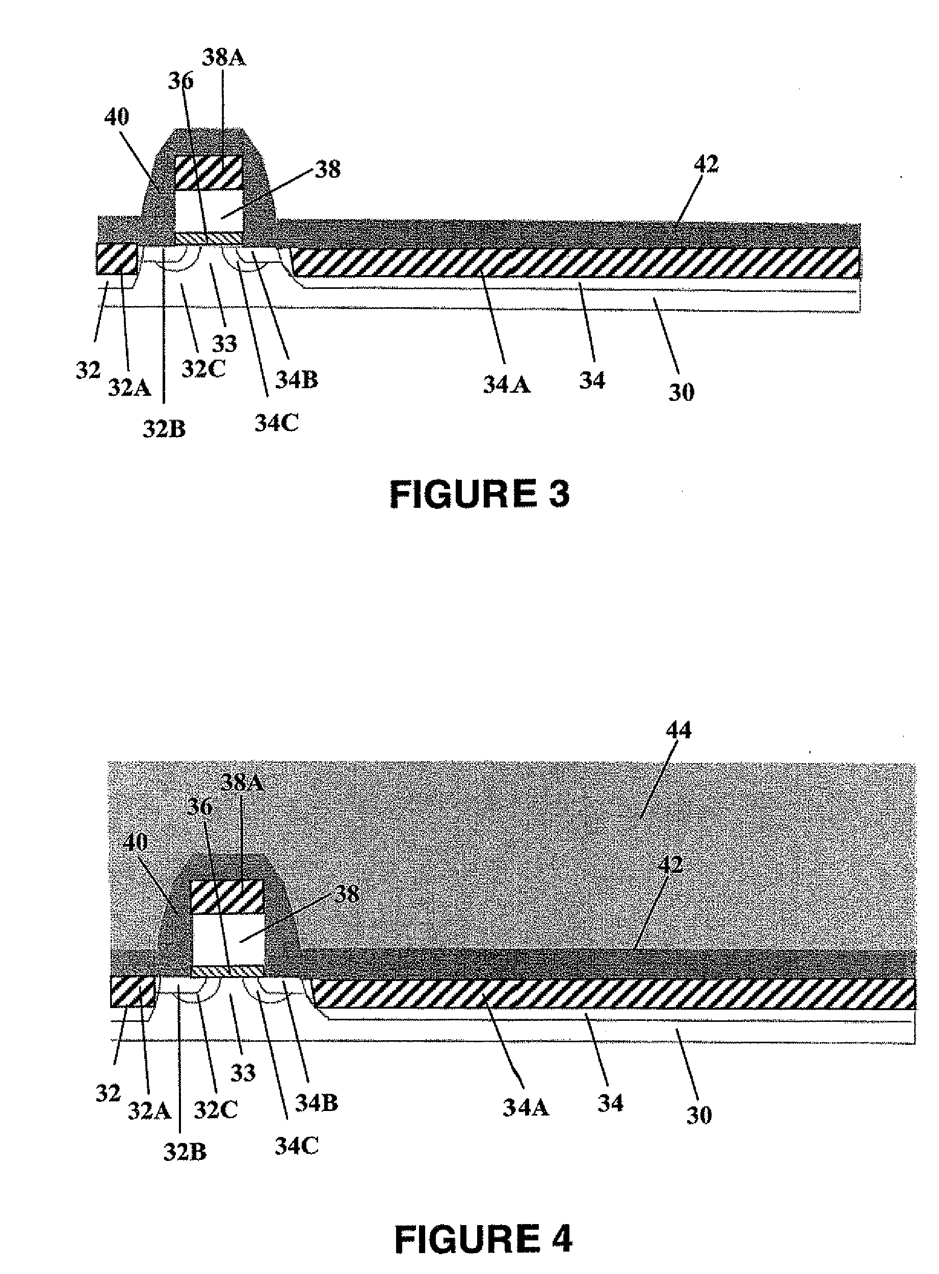
The present invention relates to an field effect transistor (FET) comprising an inverted source / drain metallic contact that has a lower portion located in a first, lower dielectric layer and an upper portion located in a second, upper dielectric layer. The lower portion of the inverted source / drain metallic contact has a larger cross-sectional area than the upper portion. Preferably, the lower portion of the inverted source / drain metallic contact has a cross-sectional area ranging from about 0.03 μm2 to about 3.15 μm2, and such an inverted source / drain metallic contact is spaced apart from a gate electrode of the FET by a distance ranging from about 0.001 μm to about 5 μm.

Description

RELATED APPLICATIONS [0001] This application is a divisional of U.S. patent application Ser. No. 11 / 163,523, filed Oct. 21, 2005.FIELD OF THE INVENTION [0002] The present invention relates to an improved field effect transistor (FET), and more particularly to an improved metal-oxide-semiconductor field-effect transistor (MOSFET) having an inverted source / drain metallic contact, and methods for fabricating such an FET device. BACKGROUND OF THE INVENTION [0003] In the semiconductor industry, there is a constant demand to increase the operating speed of integrated circuits (IC s). This increased demand is fueled by the need for electronic devices such as computers to operate at increasingly greater speeds. The demand for increased speed, in turn, has resulted in a continual size reduction of the semiconductor devices. Specifically, the channel length, junction depths, and / or gate dielectric thickness of field effect transistors (FETs) are reduced, which leads to increased density and n...

Claims


Application Information

Patent Timeline
Patent Type & Authority Applications(United States)
IPC IPC(8): H01L29/78H01L21/336
CPCH01L21/76804H01L29/6659H01L29/7833H01L2924/0002H01L2924/00H01L21/76816H01L23/485H01L21/768H01L21/18
Inventor BELYANSKY, MICHAEL P.CHIDAMBARRAO, DURESETICLEVENGER, LAWRENCE A.KUMAR, KAUSHIK A.RADENS, CARL
Owner INT BUSINESS MASCH CORP
Why Eureka
Try Eureka