

Charge-Preventing Optical Film, Charge-Preventing Adhesive Optical film, Manufacturing Method Thereof, and Image Display Device
a technology of adhesive optical film and charge-preventing film, which is applied in the direction of identification means, instruments, polarising elements, etc., can solve the problems of affecting the alignment of liquid crystals, causing defects, and disassembly and assembly of circuits
- Summary
- Abstract
- Description
- Claims
- Application Information
AI Technical Summary
Benefits of technology
Problems solved by technology
Method used
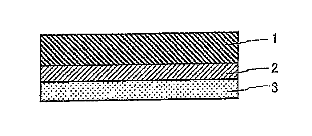
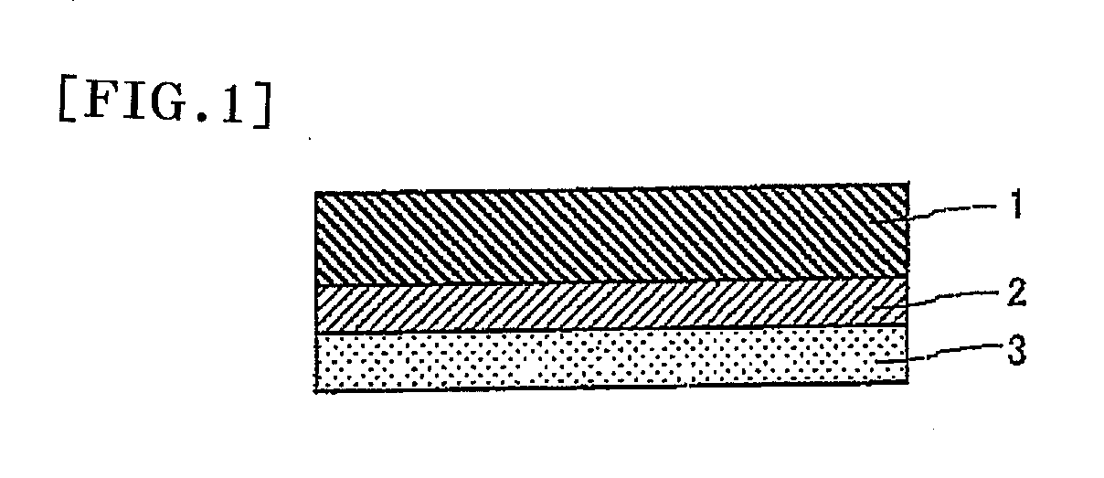
Image

Examples
example 1
Production of Optical Film
[0106] A polyvinyl alcohol film having a thickness of 80 μm was stretched 5 times in an iodine aqueous solution at 40° C., and subsequently was dried for 4 minutes at 50° C. to obtain a polarizer. A triacetyl cellulose film was adhered on both sides of this polarizer using a polyvinyl alcohol-based adhesive to obtain a polarizing plate. A rubbing treatment was performed to one side of the polarizing plate using a rubbing roll having a rubbing cloth made of rayon (made by Yoshikawa Processing Co. Ltd.) wound around a roll, under conditions of a rubbing angle of 0° C. to a slow axis of the polarizing plate, a pushing depth of 0.2 mm and 1500 rpm of number of rotation of the roll, and a film traveling rate of 8 m / min.
Formation of Antistatic Layer
[0107] An aqueous solution (manufactured by Nagase ChemteX Corporation, Denatron P-502RG, 0.8% of solid concentration) containing a water soluble polythiophene-based conductive polymer was applied to a rubbing treat...
example 2
Production of Optical Film
[0110] A polyvinyl alcohol film having a thickness of 80 μm was stretched 5 times in an iodine aqueous solution at 40° C., and subsequently was dried for 4 minutes at 50° C. to obtain a polarizer. A triacetyl cellulose film was adhered on both sides of this polarizer using a polyvinyl alcohol-based adhesive to obtain a polarizing plate.
Formation of Antistatic Layer
[0111] An aqueous solution (manufactured by Nagase ChemteX Corporation, Denatron P-502RG, solid concentration of 0.8%) containing a water soluble polythiophene-based conductive polymer was applied to one surface of the above-described polarizing plate so as to have a thickness of 50 nm after drying, and was dried for 2 minutes at 80° C. to form an antistatic layer. Subsequently, rubbing treatment was performed on a surface of the antistatic layer using a rubbing roll having a rubbing cloth made of rayon (made by Yoshikawa Processing Co. Ltd.) wound around a roll, under conditions of a pushing d...
reference example 1
[0116] An antistatic pressure-sensitive adhesive polarizing plate was produced by the same method as in Example 1, except for having changed a rubbing angle to a slow axis of a polarizing plate into 20° C. from 0° C. in formation of the optical film of Example 1.
[0117] The antistatic pressure-sensitive adhesive optical films obtained by the above-described Examples and Comparative examples were evaluated for following items. Table 1 shows evaluation results.
Light Transmittance
[0118] The produced antistatic pressure-sensitive adhesive optical film or the pressure-sensitive adhesive optical film was punched into a size of 25 mm×50 mm using a Thomson stamping die. This was adhered to a glass surface to obtain a sample. The sample was measured for light transmittance using an integrating sphere type spectral transmittance measuring instrument (made by Murakami Color Research Laboratory, DOT-3).
Antistatic Effect
[0119] The produced antistatic pressure-sensitive adhesive optical film ...
PUM
| Property | Measurement | Unit |
|---|---|---|
| Angle | aaaaa | aaaaa |
| Depth | aaaaa | aaaaa |
| Time | aaaaa | aaaaa |
Abstract
Description
Claims
Application Information