Rotary adsorbers for continuous bulk separations

a bulk separation and adsorption technology, applied in the direction of separation process, dispersed particle separation, chemistry apparatus and processes, etc., can solve the problems of limiting their use, difficult, even on a lab scale, to obtain uniform thermal activation through monoliths, etc., to achieve more effective and efficient bulk separation, hinder adsorption of target species, and maximize the flow of electric current

Inactive Publication Date: 2008-02-28
UT BATTELLE LLC
View PDF17 Cites 18 Cited by
  • Summary
  • Abstract
  • Description
  • Claims
  • Application Information

AI Technical Summary

Benefits of technology

[0018]Thus, it is an advantage of the present invention to provide a rotary adsorber wheel that can be used to replace conventional separation devices, such as distillation columns, for the bulk separation of volatile organic compounds and gases.
[0019]It is another advantage to provide a rotary adsorber wheel that uses electric swing regeneration and activated carbon fibers that are aligned in a honeycomb adsorbent structure such that the lengthwise alignment of the activated carbon fibers is essentially parallel to the direction of gas flow through the adsorbent medium, thereby maximizing flow of electric current in this direction. Concomitantly, electric current flow is minimized in the undesired, counter-productive direction of across or around the wheel, which would hinder adsorption of the target species.
[0020]It is yet another advantage to provide an adsorbent media structure configured for minimum pressure drop with a pore size distribution tailored to capture of the target volatile organic carbon (or gas) species, thereby facilitating more effective and efficient (lower energy input) bulk separations of such species.
[0021]The present invention leverages rotary solvent concentrator wheel technology for novel separations on bulk scales and with continuous, cost-savings operation. There is reduced energy consumption for bulk separations as electrical swing regeneration of the adsorbent is more energy-efficient compared to thermal swing. The overall separations process can be carried out without large temperature variations, resulting in much less degradation of thermally-labile organics. The invention also permits higher temperatures of regeneration that are not possible with paper-based honeycomb systems.
[0022]The present invention provides for faster cycling of adsorption-desorption operations under near isothermal conditions and therefore provides for more energy-efficient processing. Direct heating of the adsorbent bed (not of gas phase) allows for such operation. In the invention, the adsorbents are preferably configured in honeycomb form for minimum pressure drop and fast adsorption kinetics. Adsorption can be from both gas and liquid phases. As well as for the gas phase, electrical swing regeneration in liquid phase is possible. Liquid phase desorption / regeneration can be accomplished using a suitable solvent, including water (equivalent of using air or other gas for gas phase desorption / regeneration).
[0023]These and other features, aspects, and advantages of the present invention will become better understood upon consideration of the following detailed description, drawings and appended claims.

Problems solved by technology

In comparison, monolithic materials exhibit relatively high pressure drop which restricts their use to applications in which high gas flow rates are not a factor.
Many VOCs of even moderate molecular weight necessitate the use of mesoporous activated carbon for adsorption, and many prior processes (as currently practiced) are not amenable to the production of wider pore carbons or the very high surface area products which can be produced through chemical activation techniques (e.g., 3,000 m2 / g determined by the BET method according to a nitrogen adsorption method).
Furthermore, it is very difficult, even on a lab scale, to obtain uniform thermal activation through monoliths; i.e., with respect to surface area and porosity.

Method used


Image

  • Rotary adsorbers for continuous bulk separations
  • Rotary adsorbers for continuous bulk separations

Examples


Embodiment Construction

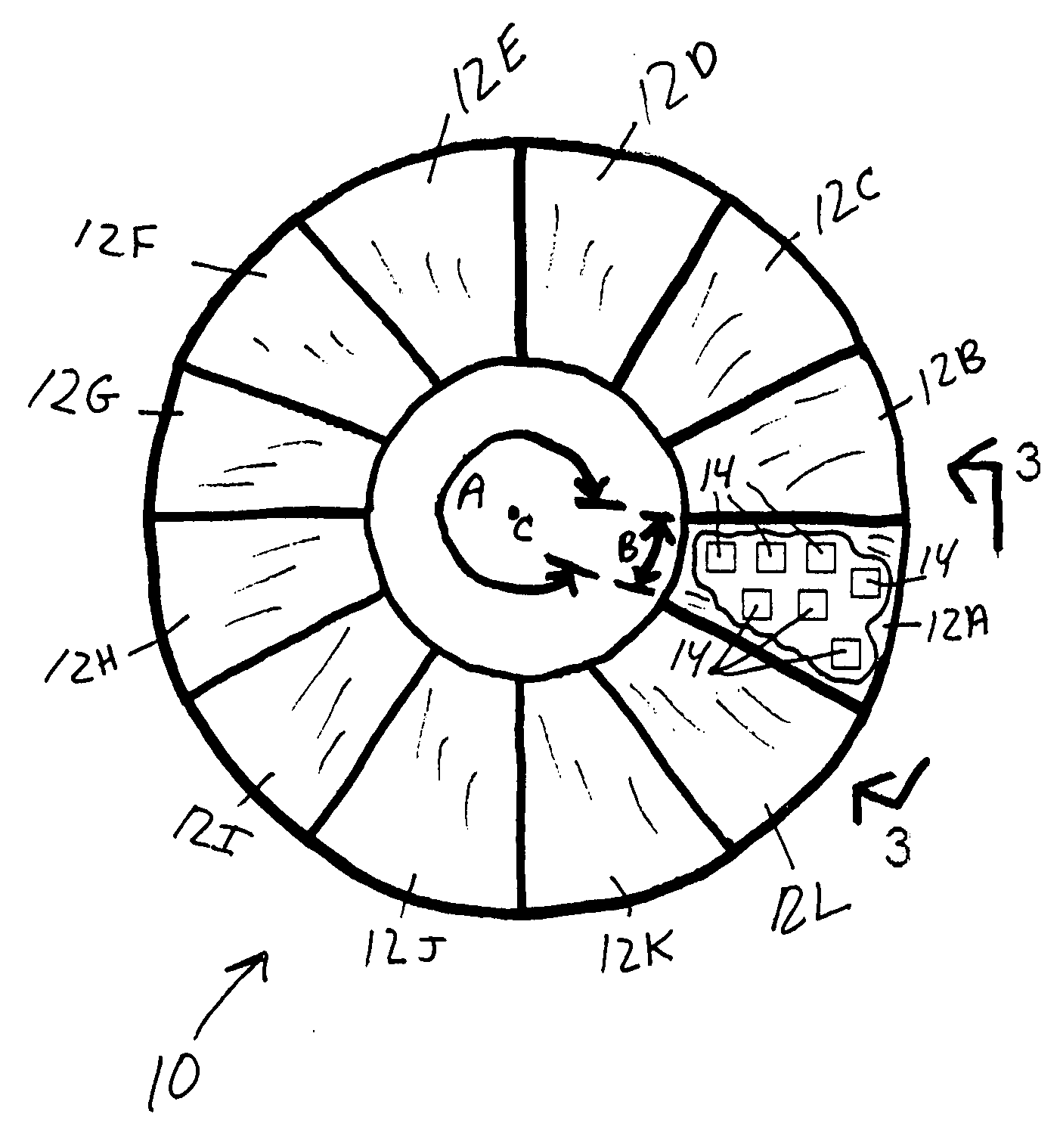
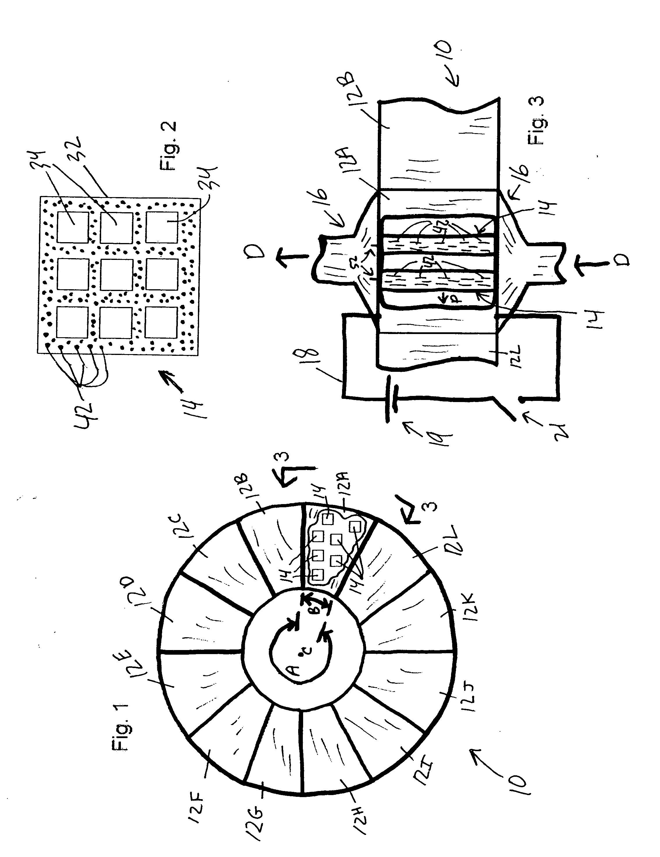
[0028]A rotary adsorber wheel according to the invention comprises an electrically-conductive adsorbent in the physical form of a monolith having internal passageways, notably a honeycomb or other suitable form, configured as a wheel. For most applications, the adsorbent in the honeycomb includes largely an activated carbon material, notably activated carbon fibers, bonded with a suitable organic or inorganic binder. A fluid stream, typically air, containing the target volatile organic (or inorganic) species to be separated is passed through the adsorption zone (typically 330 degrees of arc) of the rotating wheel, where certain of the species are adsorbed on the adsorbent. The porosity and surface chemistry of the adsorbent are tailored to the capture of specific chemical species. Species not adsorbed pass through the wheel, thereby achieving separation. Further separations on the species discharged from the adsorption zone could be achieved by passing the effluent gas stream throug...


PUM

PropertyMeasurementUnit
temperatureaaaaaaaaaa
diameteraaaaaaaaaa
diameteraaaaaaaaaa

Abstract

A rotary adsorber for continuous bulk separations is disclosed. The rotary adsorber includes an adsorption zone in fluid communication with an influent adsorption fluid stream, and a desorption zone in fluid communication with a desorption fluid stream. The fluid streams may be gas streams or liquid streams. The rotary adsorber includes one or more adsorption blocks including adsorbent structure(s). The adsorbent structure adsorbs the target species that is to be separated from the influent fluid stream. The apparatus includes a rotary wheel for moving each adsorption block through the adsorption zone and the desorption zone. A desorption circuit passes an electrical current through the adsorbent structure in the desorption zone to desorb the species from the adsorbent structure. The adsorbent structure may include porous activated carbon fibers aligned with their longitudinal axis essentially parallel to the flow direction of the desorption fluid stream. The adsorbent structure may be an inherently electrically-conductive honeycomb structure.

Description

STATEMENT REGARDING FEDERALLY SPONSORED RESEARCH[0001]This invention was made with United States Government support under Contract No. DE-AC05-00OR22725 between the United States Department of Energy and U.T. Battelle, LLC. The United States Government has certain rights in this invention.CROSS-REFERENCES TO RELATED APPLICATIONS[0002]Not Applicable.BACKGROUND OF THE INVENTION[0003]1. Field of the Invention[0004]This invention relates to an adsorption system for continuous bulk separations where separation of a species in a fluid stream is accomplished through continuous selective adsorption onto an adsorbent and subsequent desorption of the species from the adsorbent.[0005]2. Description of the Related Art[0006]The potential of adsorption systems for bulk separations has not been realized on industrially significant scales. Despite inherently low thermal efficiencies, distillation is still the operation of choice for bulk separation of a broad range of compounds. Adsorption separati...

Claims


Application Information

Patent Timeline
Patent Type & Authority Applications(United States)
IPC IPC(8): B01D53/06
CPCB01D53/06B01D2253/102B01D2253/3425B01D2253/31B01D2253/306
Inventor BAKER, FREDERICK S.
Owner UT BATTELLE LLC
Why Eureka
Try Eureka