
Separation Method For Multi Channel Electrophoresis Device Having No Individual Sample Wells

a multi-channel electrophoresis and separation method technology, applied in the direction of isotope separation, electrolysis, diaphragm, etc., can solve the problems of increasing the arrangement density of separation tubes, increasing the cost of processing injection tubes, and increasing the difficulty of radial design

Inactive Publication Date: 2008-02-28
KOREA RES INST OF STANDARDS & SCI
View PDF14 Cites 4 Cited by
  • Summary
  • Abstract
  • Description
  • Claims
  • Application Information

AI Technical Summary

Benefits of technology

[0006] The present invention is to solve the above-described problems. Therefore, it is an object of the present invention to provide a method of implementing a creative sample introduction technique that is necessary for the practical use of a microminiaturized multi-channel electrophoresis device having a simple structure from which individual sample wells or cross-shaped paths are removed from the beginning.
[0007] It is another object of the present invention to provide a method of injecting samples more effectively by using a simple-structured electrophoresis device that can be manufactured at a low cost with a high-density separation tubes according to the prior application filed by the present inventors [Korean Patent Application No. 2004-40408] installed.
[0008] It is still another object of the present invention to provide an effective method and a device of separation of samples enabling the change of the lengths of chips variously as needed taking advantage of the fact that separation tubes are arranged in the form of parallel straight lines.
[0011] In other words, one characteristic of the present invention is to include a step of preventing diffusion by storing a non-polar solvent in a sample storage tub and inputting samples into this non-polar solvent storage tub. It is preferable to use a non-polar oil such as silicon oil, mineral oil, etc. which are viscous as the non-polar solvent used for the present invention, more preferably, silicon oil. The viscosity of the non-polar solvent to be used is not greatly limited, and therefore, can be selected and used properly.
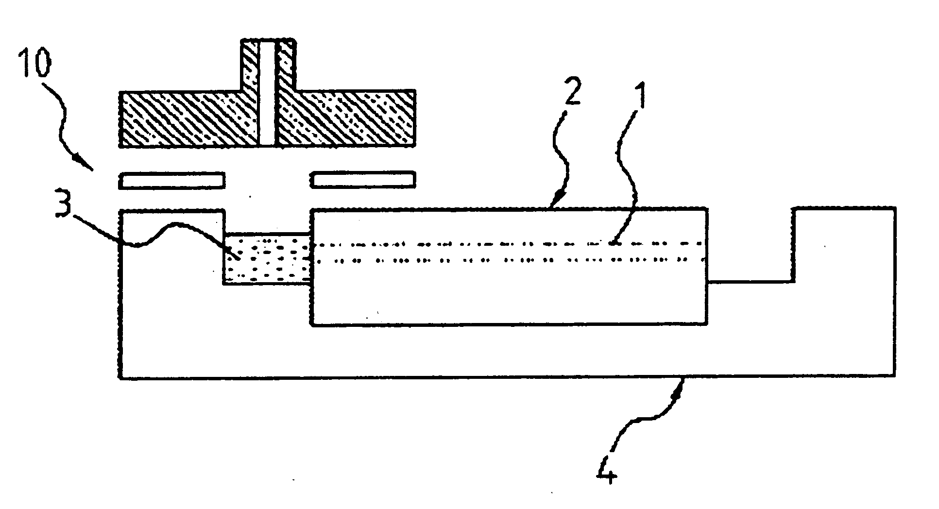
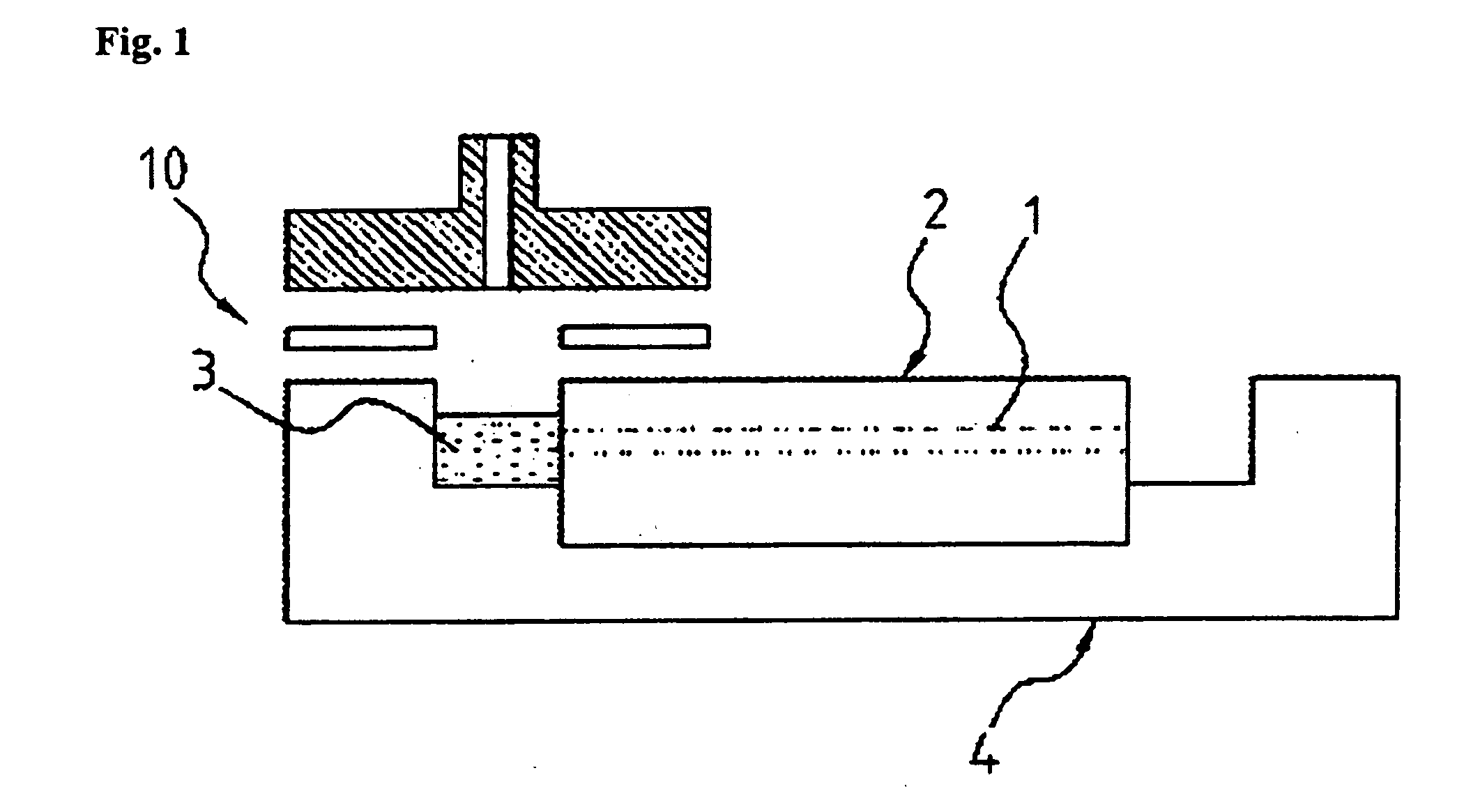
[0022] In order to prevent thus ejected samples from being diffused during the process of introduction into the separation tubes, the buffer solution storage tub at the side of the sample introduction port is filled with a non-polar solvent (such as silicon oil, mineral oil, polyolefin oligomer, etc.) in advance. It has been found that proteins or DNAs have not been diffused in the solvent in the storage tub as the time has passed if a non-polar solvent has been used. Such fact has contributed to obtaining remarkable effects of having advantages that it has not been necessary to have sample introduction apparatus such as the conventional complicated cross-shaped paths or individual storage tubs, and the separation of the samples has been done more precisely by blocking problems such as diffusion in each storage tub, etc. from the beginning. FIG. 5 shows an example in which the sample ejected maintains its shape without being diffused even as the time passes by according to the present invention. As shown in FIG. 5, it is seen that the sample ejected is not diffused at all as the time passes by or its shape is not changed, which implies that the separation work may be done very precisely if non-polar solvents of the present invention such as silicon oil, etc. are used.
[0024] Each sample ejected to the front side of the corresponding separation tube is introduced into the corresponding separation tube by the negative electric field (or positive electric field) applied to the metal part of the end part of each ejection tube. A sample is introduced smoothly if the sample ejected is directly in contact with the inlet of the separation tube. FIG. 6 shows the process how samples are introduced. It is clearly seen that a specific sample is not injected into the neighboring separation tubes due to diffusion, etc. during the process of ejection. FIG. 7 is a photograph showing that samples are introduced into the neighboring tubes sequentially. It is seen that the firstly introduced sample is introduced into the separation tube of the sample very accurately without being affected by the introduction of the samples in neighboring separation tubes and without interference.

Problems solved by technology

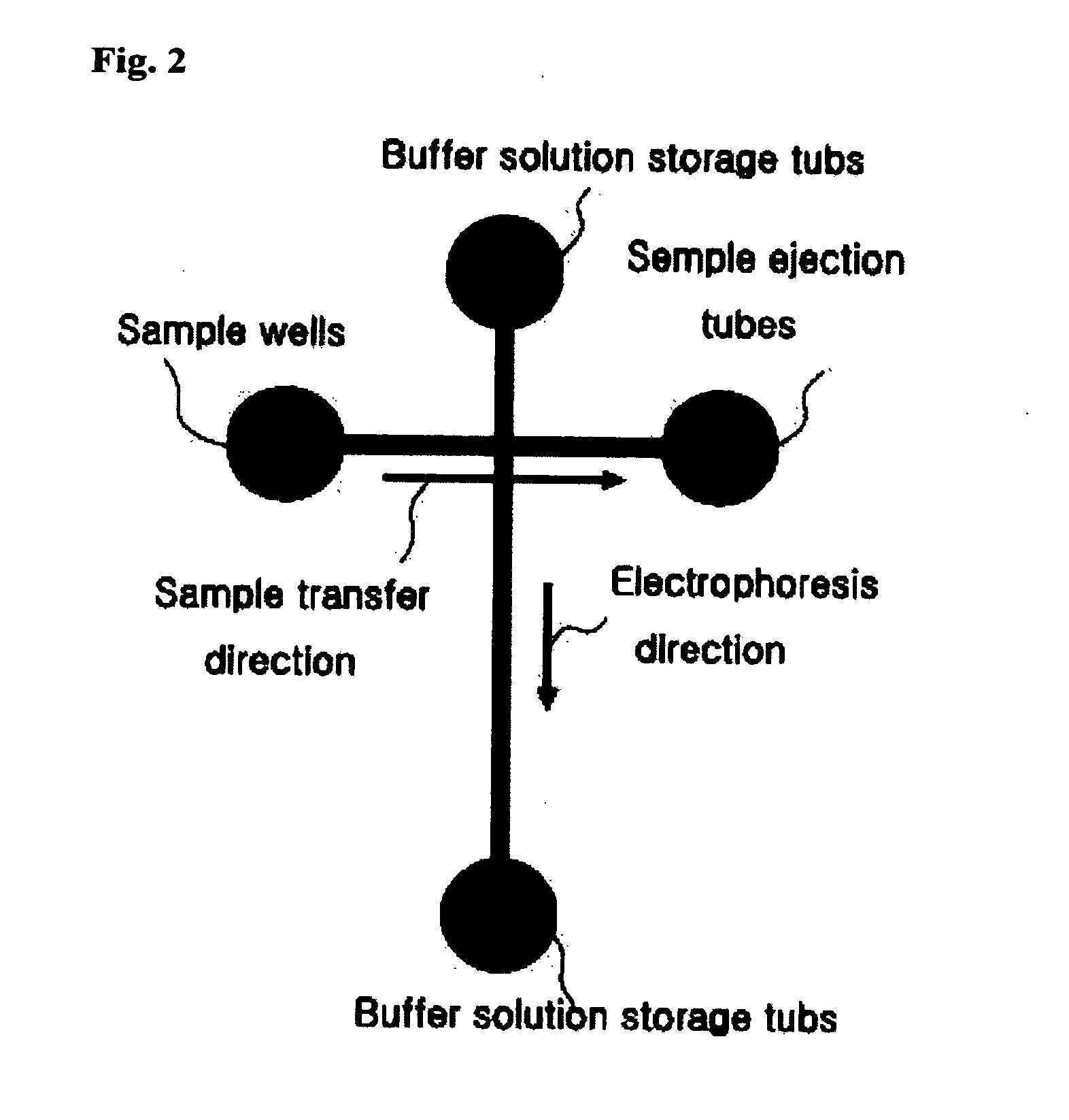
However, since the conventional technology of the injection of a sample using a cross-shaped fluid path for the introduction of a sample requires for a separate sample injection port and the formation of a cross-shaped path, it becomes complicated to arrange the separation tubes, and further, increasing the arrangement density of the separation tubes is limited.
The radial design not only adds the technical difficulty or non-economical aspects to manufacturing and cutting of the chip but also requires for the high-grade detection technique of operation while rotating.
However, even in these cases, there have been problems to be pointed out that the interval between the separation tubes has been widened since individual sample injection ports that have been relatively very larger than the separation tubes have been installed on the separation tubes, and processing of the injection tubes has been costly and difficult technically.

Method used


Image

  • Separation Method For Multi Channel Electrophoresis Device Having No Individual Sample Wells
  • Separation Method For Multi Channel Electrophoresis Device Having No Individual Sample Wells
  • Separation Method For Multi Channel Electrophoresis Device Having No Individual Sample Wells

Examples


Embodiment Construction

[0050] Injection and Separation of DNA Samples using Multi-Channel Electrophoresis

[0051] Feasibility of the above-described methods by applying the following conditions is experimented. An electrophoresis chip is a chip having 24 capillary channels. Capillary channels having an inner diameter of 100 μm and a length of 30 mm are used for the electrophoresis chip. And the channels are filled with 3% polyethylene oxide (PEO, Aldrich Company) in advance.

[0052] For the electrophoresis buffer solution, 0.5×TBE buffer (45 mM tris-borate, 1 mM EDTA, pH 8.0) corresponding to a usual buffer solution is used, and a mixed solution of 100, 200, 300, 400, 500, 600, 800, and 1,000 bp DNAs is used for the sample to be separated.

[0053] Silicon oil is injected into the storage tub of the electrophoresis device as a non-polar solvent, and the sample is injected into the capillary tubes which are analysis tubes by applying 200 V for 20 seconds to the ends of the ejection tubes of the sample. After t...


PUM

PropertyMeasurementUnit
Diameteraaaaaaaaaa
Diameteraaaaaaaaaa
Lengthaaaaaaaaaa

Abstract

The present invention is related to a method of separation of compounds by electrophoresis in which the compounds such as genes, proteins, etc. may be analyzed very precisely as samples are introduced directly into the separation tubes of the chip at the collection site, and therefore, it is not necessary to have separate fluid paths or individual sample storing apparatus that have been necessary for the conventional electrophoresis; it is easy to make the chips as the structure of the chip becomes extremely simple, and high-density arrangement of the separation tubes is enabled; and further, the compounds such as genes, proteins, etc. may be analyzed very precisely without interference in the storage tubs by using a non-polar solvent as the solvent of the sample storage tub.

Description

TECHNICAL FIELD [0001] The present invention is related to a method of separation of compounds by electrophoresis in which the compounds such as genes, proteins, etc. may be analyzed very precisely as samples are introduced directly into the separation tubes of the chip at the collection site, and therefore, it is not necessary to have separate fluid paths or individual sample storing apparatus that have been necessary for the conventional electrophoresis; it is easy to make the chip as the structure of the chip becomes extremely simple, and high-density arrangement of the separation tubes is enabled; and further, the compounds such as genes, proteins, etc. may be analyzed very precisely without interference in the storage tubs by using a non-polar solvent as the solvent of the sample storage tub. [0002] The present invention is related to a technology of performing electrophoresis by using a microminiaturized multi-channel electrophoresis device. The microminiaturized multi-channel...

Claims


Application Information

Patent Timeline
IPC IPC(8): B01D57/02
CPCG01N27/44782B01L9/527G01N27/44791G01N27/4473G01N33/0022
Inventor PARK, SANG-RYOULYANG, IN-CHULKIM, YOUNG-HO
Owner KOREA RES INST OF STANDARDS & SCI
Learn More