Color wheel unit

a color wheel unit and color wheel technology, applied in the field of color wheel units, can solve the problems of high wind noise, high temperature inside the display device, and possible damage to the reliability of the motor b>10/b>, so as to prevent the unit from getting heated remarkably high, increase the heat radiation area, and effectively cool the

Inactive Publication Date: 2008-02-28
MINEBEA CO LTD
View PDF4 Cites 29 Cited by
  • Summary
  • Abstract
  • Description
  • Claims
  • Application Information

AI Technical Summary

Benefits of technology

[0019]Also, when the first protrusion structure provided at the outer circumferential surface of the rotor revolves with the rotation of the motor, airflow is caused inside the case. Consequently, even if the case is hermetically closed, the heat generated inside the case can be dispersed by the airflow, and the color wheel unit is prevented from getting heated remarkably high at a certain limited area.
[0020]And, if the case is structured so as to allow air circulation between inside and outside the case, the heat generated inside the case can be let out with the airflow. With such a case structure, the first and second protrusion structures provided inside the case not only constitute heat transmission paths from the inside of the case to the outer surface of the case as described above but also function as radiation fins for dissipating the heat of the rotor and the heat of the case, respectively, thus increasing the heat radiation area of the color wheel unit and also effectively cooling the color wheel unit from inside the case.
[0021]In the aspect of the present invention, the first and second protrusion structures may each include a surface oriented slant with respect to the plane orthogonal to the rotary shaft of the rotor. As a result, the airflow generated by the revolving of the first protrusion structure includes an axial flow component thereby effectively dispersing the heat inside the case. Also, the above-described overlapping between the first and second protrusion structures is retained so as to maintain a sufficient thermal binding therebetween and to reduce

Problems solved by technology

Thus, the color wheel 3 operates to color-separate sequentially the light from the lamp 1 while rotating rapidly, and this operation gives a problem that a high wind noise is generated due to the rapid rotation.
In a projection display device, a high pressure mercury lamp with high output is often used as the lamp 1 in order to produce an adequately bright projection image, which results in providing a problem that the temperature inside the display device becomes high due to the radiation heat from the lamp 1.
Consequently, the temperature ins

Method used


Image

  • Color wheel unit
  • Color wheel unit
  • Color wheel unit

Examples


Embodiment Construction

[0032]An exemplary embodiment of the present invention will be described with reference to the accompanying drawings.

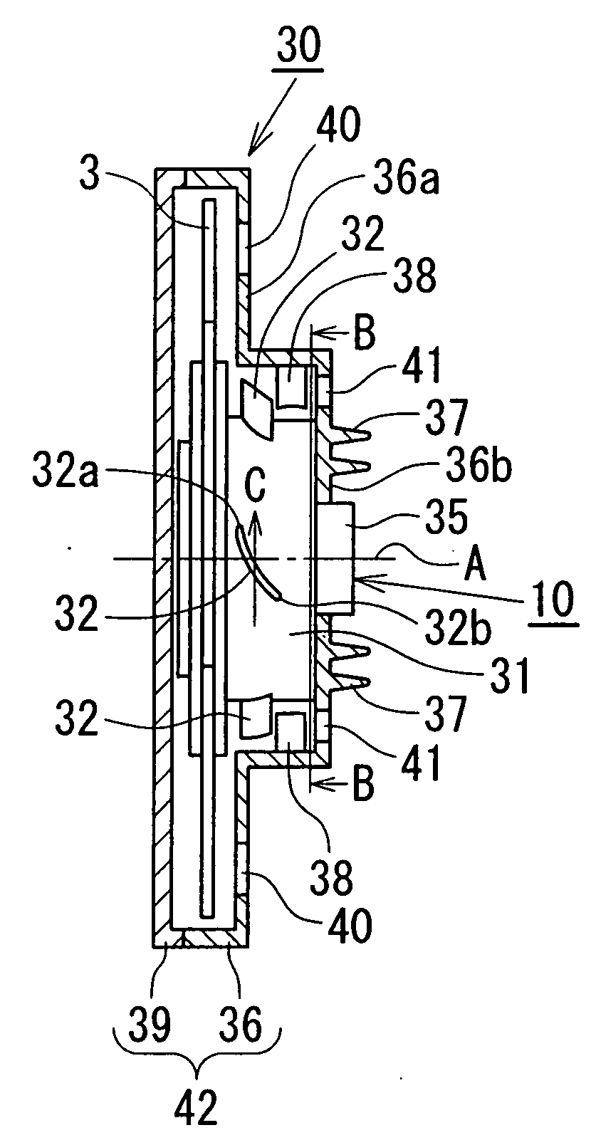
[0033]Referring to FIG. 1, a color wheel unit 30 includes a color wheel 3, a motor 10, and a case 42 to house the color wheel 3 and the motor 10. The color wheel 3 is composed of a plurality of sector-shaped color filter segments put together in a disk configuration. Each of the color filter segments is structured such that a dielectric multilayer film to transmit a light having a specific (red / green / blue) wavelength is formed on a sector-shaped substrate made of a light transmittable material such as optical glass.

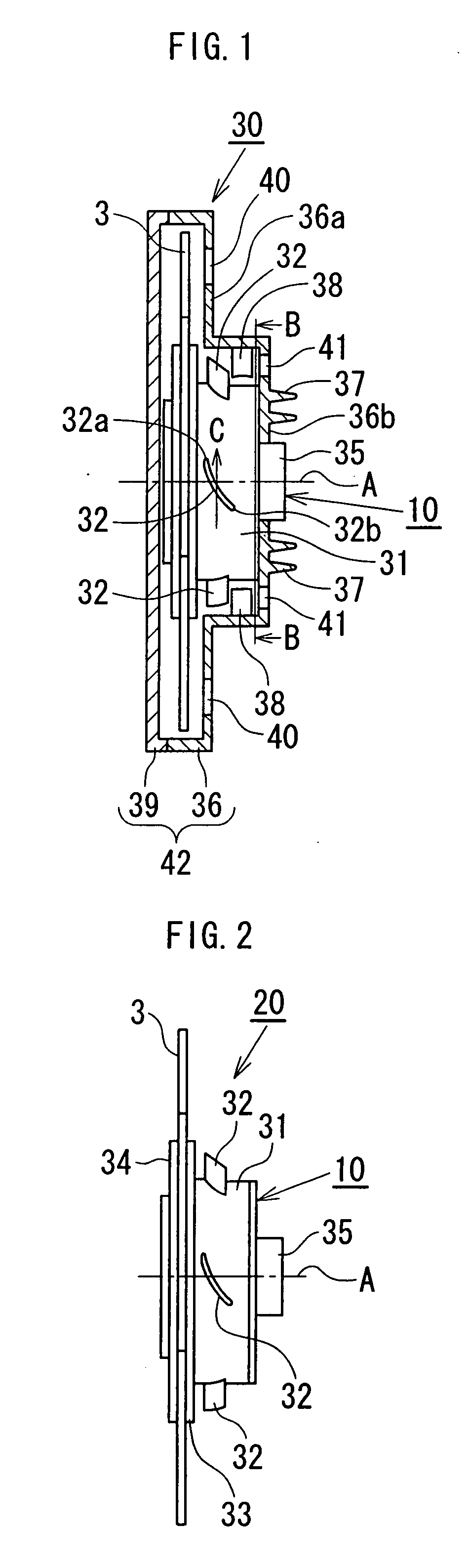
[0034]Referring also to FIG. 2, the motor 10 is an outer rotor brushless DC motor principally including a stator core (not shown), and a rotor 31 having a rotor magnet opposing the outer circumference of the stator core, wherein a flange 33 is fixedly attached to a hub (not shown) which is fixed to a rotary shaft (not shown) of the rotor 31. The color filte...


PUM


Abstract

A color wheel unit includes: a color wheel including a plurality of color regions; a motor adapted to rotate the color wheel and including a rotor with a rotary shaft; and a case adapted to house the color wheel and the motor and including a heat radiating means disposed at the outer surface of the case. In the color wheel unit, a first protrusion structure extending radially outwardly is disposed at the outer circumferential surface of the rotor, and a second protrusion structure extending radially inwardly is disposed at the inner surface of the case, wherein the projection area of the second protrusion structure on the plane orthogonal to the rotary shaft of the rotor is overlapped at least partly with the projection area of the first protrusion structure on the plane orthogonal to the rotary shaft of the rotor.

Description

BACKGROUND OF THE INVENTION[0001]1. Field of the Invention[0002]The present invention relates to a color wheel unit used in a projection display device to project a color image on, for example, a screen by a time division system or a color sequential system.[0003]2. Description of the Related Art[0004]A projection display device is adapted to display a picture image in such a manner that a white light emitted from a light source is separated into three primary colors, specifically, red, green and blue color lights by a color wheel, then the red, green and blue color lights are modulated into red, green and blue image lights by an optical modulator, such as a liquid crystal panel and DMD (digital micro-mirror device), and the red, green and blue image lights are projected onto a screen or the like.[0005]FIG. 4 is a schematic view of a conventional projection display device which includes: an illumination system composed of a lamp 1, a reflector mirror 2, a color wheel 3, a rod lens 4...

Claims


Application Information

Patent Timeline
IPC IPC(8): G02B5/22
CPCG02B26/008G02B7/008
Inventor NIWA, SHINICHI
Owner MINEBEA CO LTD
Why Eureka
Try Eureka