Optical multi-layer sheet and image display device

a multi-layer sheet and optical technology, applied in non-linear optics, instruments, synthetic resin layered products, etc., can solve the problems of easy flaws in applying materials to the surface of the base material, decrease in image quality, and occurrence of flaws, etc., to achieve excellent resistance to flaws, improve lubricating properties, and enhance mechanical strength

Inactive Publication Date: 2008-03-06
FUJIFILM CORP
View PDF5 Cites 12 Cited by
  • Summary
  • Abstract
  • Description
  • Claims
  • Application Information

AI Technical Summary

Benefits of technology

[0007] In view of the above, an object of the present invention is to provide an optical multi-layer sheet having high degree of transparency, resistance to flaws on its surface, and an image display device using the same.
[0014] According to the multi-layer sheet of the present invention, the protective material is formed on the second layer of the base material formed of polyester. The base material has the optical functional layer as the optical sheet formed on the first surface. The protective material includes fine particles, a lubricant, and a binder. The fine particles are formed of organic compound or inorganic compound. The binder is a polymer having a glass transition temperature of 40° C. or more. Accordingly, upon being formed as the optical functional layer, for example, the optical diffusion layer can be used as the diffusion sheet that is a main component of the LCD backlight unit and has excellent resistance to flaws at the side of the light. Further, since the base material is biaxially stretched, the mechanical strength can be enhanced. Moreover, since the lubricant serves for improving the lubricating properties, it is possible to reduce the additional amount of the fine particles, keeping the lubricating properties, and prevent the degree of transparency from decreasing. Thereby, it is possible to provide the multi-layer sheet having high degree of transparency and excellent resistance to flaws, and the image display device achieving high definition using the multi-layer sheet.

Problems solved by technology

Further it is required that the multi-layer sheet has few flaws on the surface or has resistance to flaws, since due to minute flaws on the surface, contrast of display image is decreased and brightness unevenness occurs, thus resulting in decrease in the image quality.
However, when a multi-layer sheet is produced, the surface of the base material easily has flaws in applying materials to the surface of the base material, transporting the multi-layer sheet, or stacking the produced multi-layer sheets.
However, according to Japanese Patent Laid-Open Publication No. 2004-004598, although it is possible to decrease brightness unevenness caused by deflection or discoloration on the sheet due to heat, UV rays, or the like, it is impossible to decrease flaws caused during transportation of the sheet.
Additionally, since a large amount of fine particles are added thereto, flaws may occur by decrease in the degree of transparency or floating of the fine particles.
According to Japanese Patent Laid-Open Publication No. 2007-152887, since only the resistance to flaws at a side on which the optical functional layer is formed is improved, there arises a problem about how to improve resistance to flaws on the another side of the base material.

Method used


Image

  • Optical multi-layer sheet and image display device
  • Optical multi-layer sheet and image display device
  • Optical multi-layer sheet and image display device

Examples


example

[0079] Hereinafter, in order to explain the present invention in detail, Experiments 1 to 9 were performed as examples. However, the present invention is not limited thereto. Note that Experiments 1 to 5 are examples of the present invention, and Experiments 6 to 9 are comparative examples thereof.

experiment 1

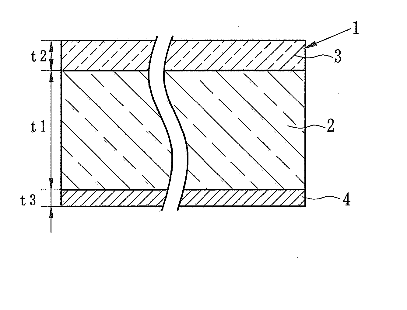
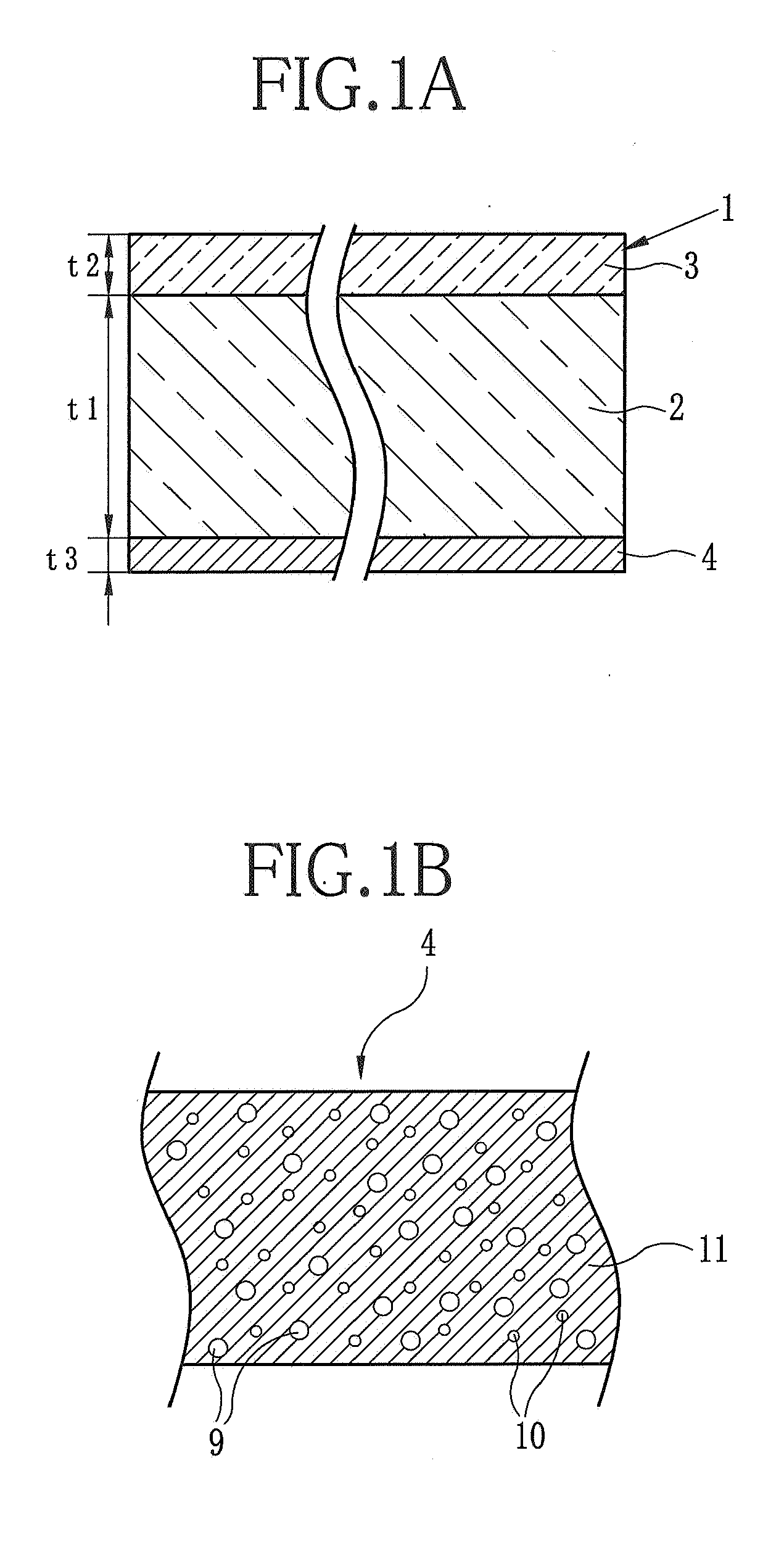
[0080] In experiment 1, an undercoat layer was formed on a first surface of the base material 2 formed of polyester, and the protective material 4 was formed on a second surface of the base material 2 such that the protective material 4 was opposed to the undercoat layer. Thus, the multi-layer sheet 1 was produced.

[0081] [Base Material]

[0082] Polyethylene terephthalate (hereinafter referred to as PET) having an inherent viscosity of 0.66 was prepared. The PET was obtained by polycondensation reaction using Ge as a catalyst. After being dried until the water content thereof became 50 ppm or less, the PET was melted inside an extruder having a heater with a temperature adjusted to approximately a constant level within a range of 280° C. to 300° C. Next, the melted PET was discharged from a die onto a chill roll subjected to electrostatic application, to obtain an amorphous film. Thereafter, the amorphous film was stretched in a transporting direction of the film by 3.1 times, and the...

experiment 2

[0094] In Experiment 2, the binder 11 for the protective material 4 was a polyester different from that in Experiment 1 (Plus coat Z687, produced by GOO CHEMICAL CO., LTD, solid content of 25%, glass transition temperature of 110° C.). Other conditions for producing the multi-layer sheet 1 were the same as those in Experiment 1.

Experimenet 3

[0095] In Experiment 3, the protective material 4 was formed under the following conditions. Other conditions for producing the multi-layer sheet 1 were the same as those in Experiment 1.

[Coating liquid for protective material]monomer (Dipentaerythritol Hexaacrylate)145 parts by mass polymerization initiator4.4 parts by mass(2,4-bis(trichloromethyl)-6-(4-N,N-diethoxycarbonylmethyl)-3-bromophenyl)-s-triazine)benzoguanamine fine particles (Epostar-M-30,1.5 parts by massproduced by NIPPON SHOKUBAI CO., LTD.,average diameter of 3 μm)lubricant (KF-412 produced by Shin-Etsu Chemical7.3 parts by massCo., LTD.)surfactant (F780F, produced by Dainippon...


PUM

PropertyMeasurementUnit
glass transition temperatureaaaaaaaaaa
diameteraaaaaaaaaa
diameteraaaaaaaaaa

Abstract

An optical functional layer is formed on a first surface of a base material formed of polyester biaxially stretched. A protective material is formed on a second surface of the base material. The protective material includes fine particles, a lubricant, and a binder. The fine particles are formed of organic compound or inorganic compound. The binder is a polymer having a glass transition temperature of 40° C. or more. The lubricating properties of the surface are improved by the lubricant. As the lubricating properties improve, a necessary additional amount of the fine particles becomes less. Thereby, it is possible to prevent the degree of transparency from decreasing. Accordingly, the multi-layer sheet having high degree of transparency and excellent resistance to flaws can be obtained. It is possible to reduce bright unevenness by using the multi-layer sheet as the diffusion sheet.

Description

FIELD OF THE INVENTION [0001] The present invention relates to an optical multi-layer sheet, and an image display device such as a liquid crystal display (LCD), a plasma display (PDP), an organic electroluminescence display (organic EL display), surface-conduction electron-emitter display (SED), a cathode ray tube display (CRT display), or the like using the optical multi-layer sheet as its component. BACKGROUND OF THE INVENTION [0002] As an image display device for achieving high definition, a LCD, a PDP, an EL display device, and the like have been attracting attention. Among them, the LCD is thinner and lighter than other image display devices. Therefore the LCD is used for a widescreen TV, portable electronics, and the like, and the demand for the LCD is drastically increasing. The LCD is mainly composed of a liquid crystal cell obtained by filling a special liquid between glass plates, and a polarizing filter. A voltage is applied to the liquid crystal cell to change orientatio...

Claims


Application Information

Patent Timeline
Patent Type & Authority Applications(United States)
IPC IPC(8): B32B5/16B32B17/06B32B27/06B32B9/04B32B27/36
CPCG02B1/105G02B5/0242Y10T428/252G02F1/133606Y10T428/254G02B5/0278Y10T428/31663Y10T428/31786G02B1/14
Inventor HATAKEYAMA, AKIRANOMURA, TATSUYAKOBAYASHI, TAKASHISUZUKI, KATSUYOSHIIMAMURA, NAOYASAIKI, TAKAFUMINISHIKAWA, SUMIO
Owner FUJIFILM CORP
Why Eureka
Try Eureka