Low friction particulate coatings

a coating and low friction technology, applied in the field of low friction coatings, can solve the problems of affecting the accuracy of stent placement, and the translation of stent movement within the catheter to be erratic and imprecise, so as to reduce the frictional force associated with movement and reduce the push force

Inactive Publication Date: 2008-03-06
SURMODICS INC
View PDF17 Cites 34 Cited by
  • Summary
  • Abstract
  • Description
  • Claims
  • Application Information

AI Technical Summary

Benefits of technology

[0029]In a related aspect, the invention provides methods for reducing the push force associated with the deployment of an implantable medical device. The method comprises a step of providing a catheter having an inner diameter coating. The inner diameter coating includes a halogenated polymeric nano- or microparticle coated layer which contacts a medical device. The method also comprises a step of providing an implantable device in contact within the inner diameter coating, and another step of moving the implantable device in contact within the inner diameter coating. The halogenated polymeric nano- or microparticle coating reduces the frictional forces associated with movement of the device.

Problems solved by technology

If the static friction force is high, the application of force can cause a sudden, rapid relative movement of the two surfaces, resulting in an imprecise and undesired movement of one or more components of the system.
These frictional forces can cause the translation of movements of the stent within the catheter to be erratic and imprecise.
Without reduction in frictional forces, stent movement and deployment may create trauma to the endothelium and may cause improper placement of the stent.
The process of stent deployment is further complicated given that control of stent deployment via stent push wires is typically carried out at the proximal end of the catheter (user end), often through a tortuous pathway to the target site.
In a coronary stent deployment system that utilizes a retractable sheath, the interaction of the sheath and guide catheter upon retraction can be problematic.
This issue is commonly dealt with by making the retractable sheath long enough so that it will be contained in the guide catheter at all times. The retraction of the sheath increases system profile, reduces flexibility, and creates excess friction upon sheath retraction.
When coated on the surface of devices, hydrophilic polymers can become lubricious.
However, hydrophilic coatings can swell considerably in the presence of water and increase the profile of the device (such at the thickness of the catheter wall, thereby decreasing the inner diameter of the catheter).
While a PTFE liner can provide a low-friction surface, it may stiffen the catheter and make it difficult to be bent during an insertion process.
Furthermore, the fabrication of catheter bodies with PTFE liners is labor intensive.
It can be very difficult to integrate PTFE into or on a prefabricated article since many thermoplastic articles are formed from polymers having different properties than PTFE.
This process, however, can be time consuming and expensive.
The preparation of useful coatings for the surfaces of medical devices is challenging.
Twisting or contortion of the device during use in the body may result in cracking, or peeling of the coating.
Furthermore, since hydrophilic coatings have the potential to swell to a certain extent in an aqueous environment, the components of the coating can potentially become dislodged and lost from the coating if not sufficiently stabilized.
Further, the dimensions and modulus of the device can be affected by coatings that are excessively thick.
Coatings are often prepared using organic solvents or low molecular weight monomeric compounds, which in some cases present toxicity concerns.
Catheters are typically subject to considerable manipulation and flexion following insertion in the body.
The coatings can be subject to a considerable amount of flexion without risk that the coatings will experience significant cracking or delamination.
Such precision can generally not be achieved using a PTFE insert.

Method used


Image

  • Low friction particulate coatings
  • Low friction particulate coatings

Examples


example 1

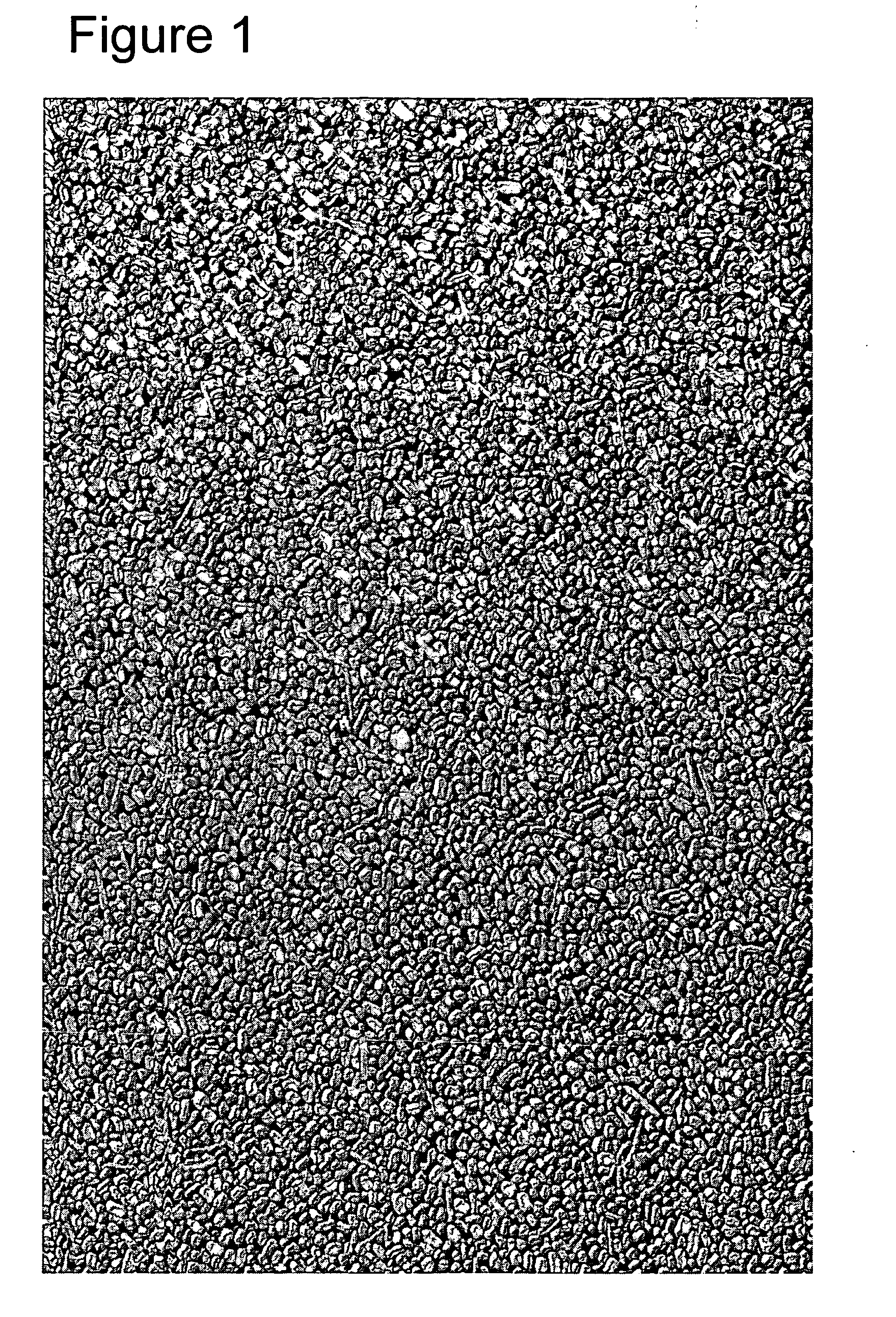
[0143]Ten centimeter pieces of 3 mm diameter Pellethane™ EG-60D polyurethane rods were wiped with propanol to clean. A working solution of 20% by volume polycarbodiimide (Carbodilite™ V-02-L2 from Nisshinbo Chemical, Japan) was prepared by diluting a 40% stock solution with propanol. The pieces were dipped into the working solution at a rate of 1.5 cm / second, left to soak for thirty seconds, then pulled out of the solution at a rate of 1.0 cm / second. After a fifteen minute air dry, the pieces were dipped into 30% solids PTFE particles (Dispersez™ 200W2 from PolySciences, Inc.) at 2.5 cm / second into the solution, left to soak for ten seconds, then pulled out at 1.0 cm / sec. All pieces were milky white in color after this coating. The pieces were allowed to dry at room temperature for twenty hours to cure the reaction between the carbodiimide and the grafted acrylic acid groups on the PTFE particles.

[0144]After curing, the pieces were placed in a stirring water bath to see if coating w...


PUM

PropertyMeasurementUnit
diameteraaaaaaaaaa
diameteraaaaaaaaaa
diameteraaaaaaaaaa

Abstract

The invention provides a low-friction halogenated nano- or microparticulate coating and method for forming the coating on articles, such as implantable medical articles. The halogenated nano- or microparticles, desirably fabricated from PTFE, are present on the surface of the coating and covalently coupled to a coupling component, which facilitates formation of the coating. The coatings are biocompatible and can be formed on a selected portion of a medical device in a straightforward process. In some aspects the nano- or microparticulate coatings are formed on a system for the insertion of a medical device, wherein the system includes a catheter.

Description

FIELD OF THE INVENTION[0001]The invention relates to low-friction coatings formed using halogenated polymeric nano- or microparticles. The invention also relates to insertable medical article including these low-friction coatings, the preparation of these articles, and uses thereof.BACKGROUND OF THE INVENTION[0002]Numerous systems include components that are moved in relation to one another. In many cases, these systems can function more efficiently by using materials that reduce frictional forces, thereby facilitating movement of the components in the system.[0003]One type of frictional force is static friction force, which is the initial resistance to movement of two components in contact with one another. Movement of one component occurs when the static friction force is overcome by application of force to at least one of the components. If the static friction force is high, the application of force can cause a sudden, rapid relative movement of the two surfaces, resulting in an ...

Claims


Application Information

Patent Timeline
Patent Type & Authority Applications(United States)
IPC IPC(8): B32B5/16B32B15/04A61L33/00B05D1/12G11B5/64
CPCA61L29/085A61L31/10Y10T428/265Y10T428/254C08L27/18Y10T428/31678Y10T428/31504
Inventor FINLEY, MICHAEL J.
Owner SURMODICS INC
Why Eureka
Try Eureka