Micro Plasma Jet Generator

Active Publication Date: 2008-03-13
JAPAN SCI & TECH CORP
View PDF3 Cites 9 Cited by
  • Summary
  • Abstract
  • Description
  • Claims
  • Application Information

AI Technical Summary

Benefits of technology

[0016]According to a generator and method of the present invention, a microplasma jet with extremely high density can be stably generated at atmospheric pressure with a small electric power of several ten watts because the power density of a microplasma section increases in inverse proportion to the volume of a discharge.
[0017]The electric power to drive the generator, which is compact, is one tenth or less of that to drive a bench-top generator, which is usuall

Problems solved by technology

Such a method has various problems that electrodes are worn, reactive gas cannot be used, and workpieces are limited to conductors.
Since it is difficult to stably generate high-de

Method used


Image

  • Micro Plasma Jet Generator
  • Micro Plasma Jet Generator
  • Micro Plasma Jet Generator

Examples


manufacture example 1

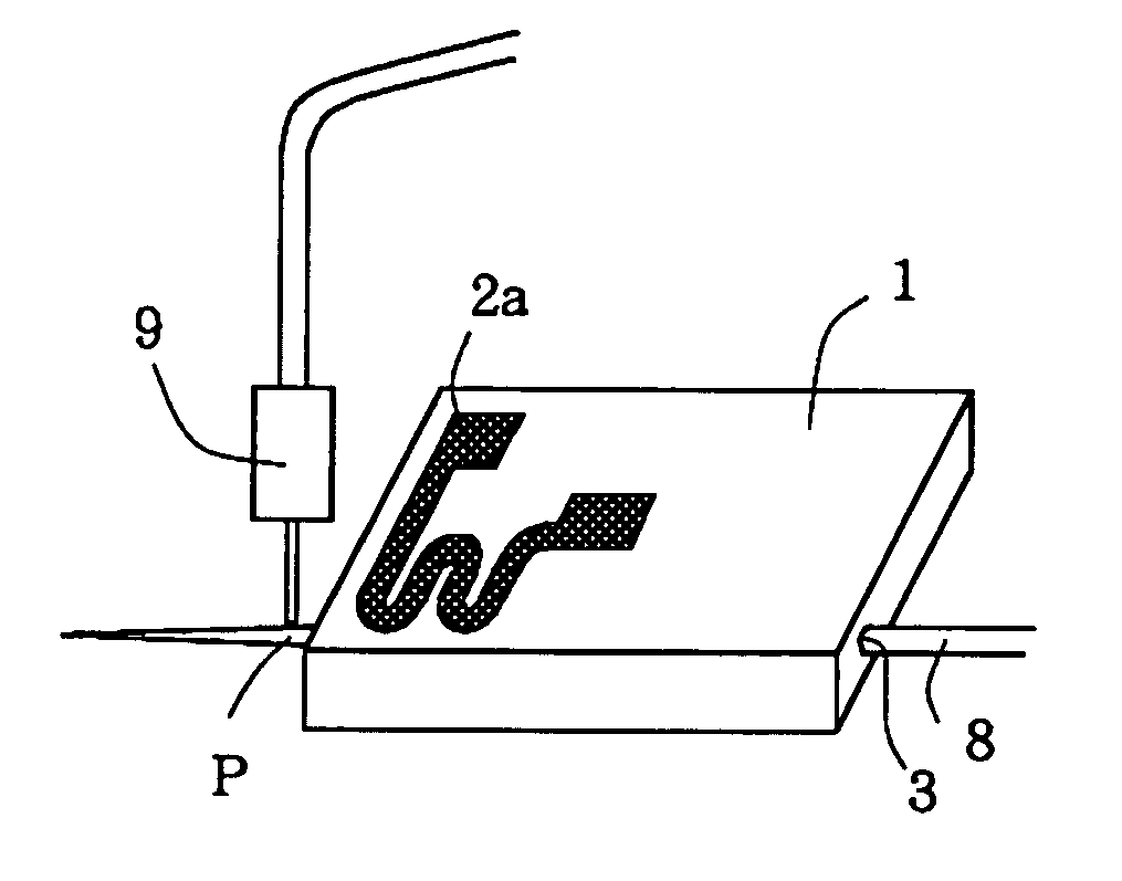
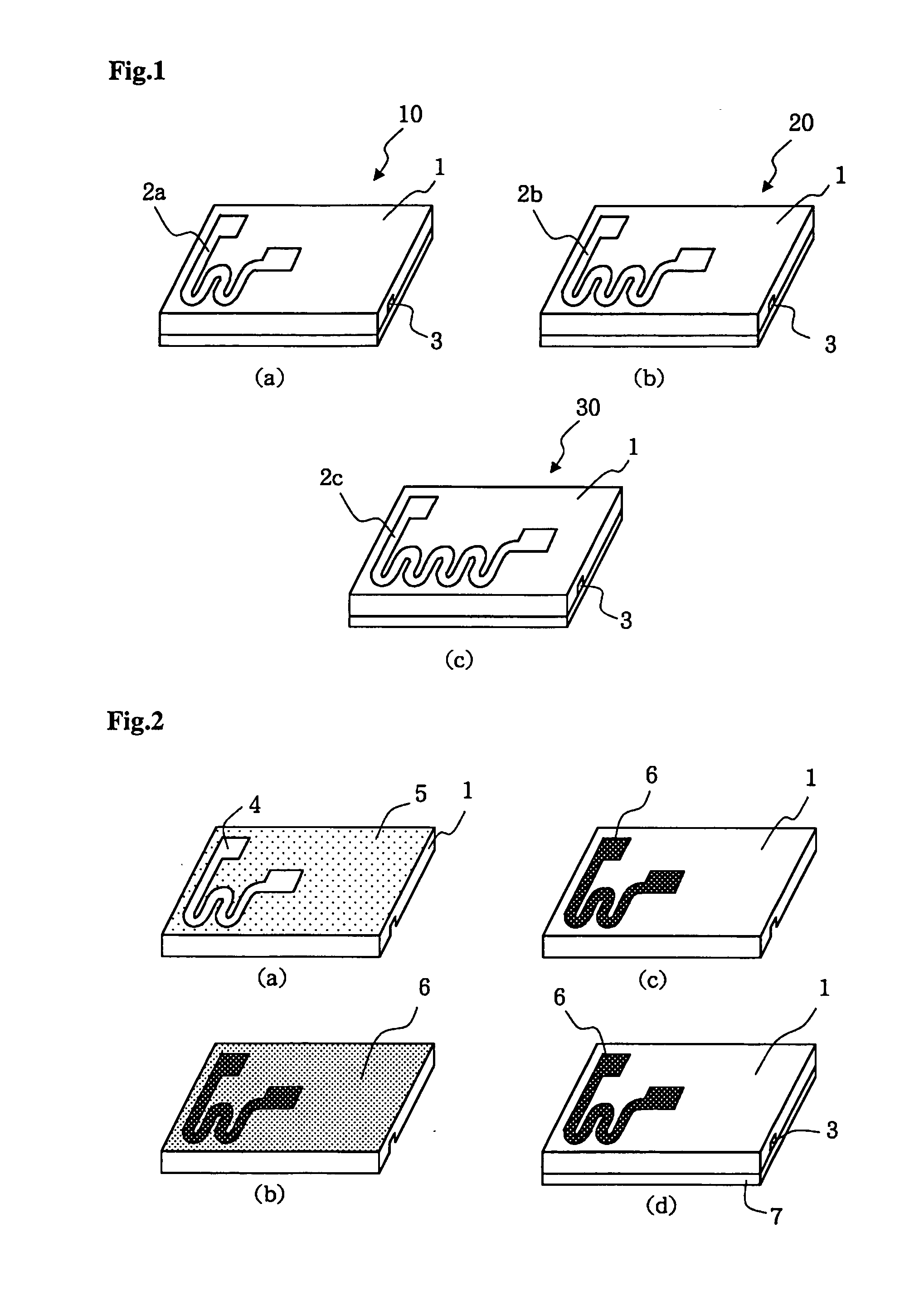
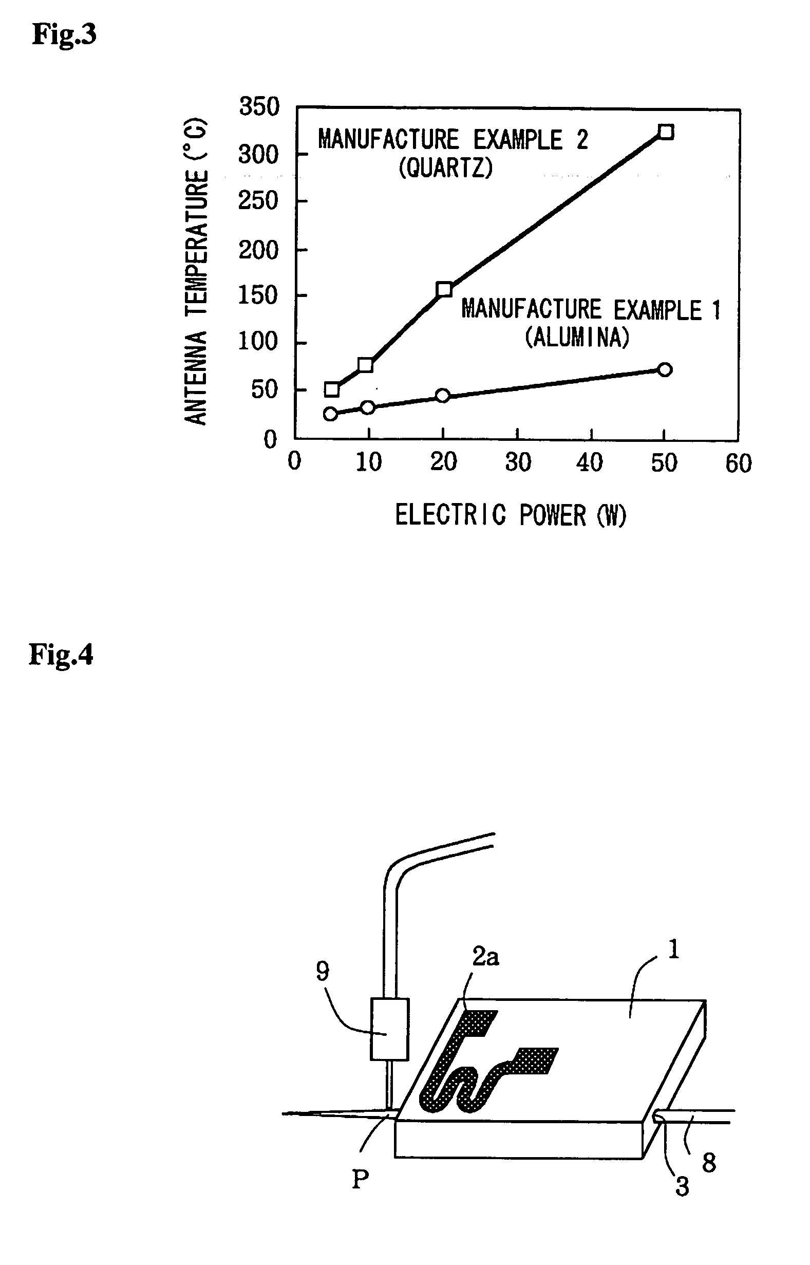
[0033]Plasma chips were manufactured according to the procedure shown in FIG. 2. In the step shown in FIG. 2(a), each resist mask 5 with an opening 4 for forming a two-turn micro-antenna was formed on an alumina substrate 1 (a length of 15 mm and a width of 30 mm). In this step, the opening 4 was formed close to a microplasma jet-generating end portion of each plasma chip. This allowed a high-density plasma jet to be generated at a portion of the micro-chip that is located close to the plasma antenna. The substrate 1 had a recessed section (a depth of 1 mm, a width of 1 mm, and a length of 30 mm), formed in the rear face thereof in advance, for forming a discharge tube.

[0034]In the step shown in FIG. 2(b), the following sublayers were formed by RF magnetron sputtering: a Cr sublayer, having a thickness of about 500 Å, serving as an adhesive layer between the substrate and a Cu sublayer and then the Cu sublayer, having a thickness of about 1000 Å, serving as a seed layer in a subsequ...

manufacture example 2

[0035]A plasma chip was manufactured in substantially the same manner as that described in Manufacture Example 1 except that a quartz substrate was used instead of the alumina substrate.

manufacture examples 3 and 4

[0036]Two plasma chips were manufactured in substantially the same manner as that described in Manufacture Example 1 except that these plasma chips each included a three-turn micro-antenna as shown in FIG. 1(b) or a four-turn micro-antenna as shown in FIG. 1(c).


PUM

PropertyMeasurementUnit
Thicknessaaaaaaaaaa
Flow rateaaaaaaaaaa
Electric potential / voltageaaaaaaaaaa

Abstract

The present invention provides a microplasma jet generator capable of stably generating a microplasma jet in a microspace at atmospheric pressure with low electric power.
The microplasma jet generator is driven with a VHF power supply to generate an inductively coupled microplasma jet and includes a substrate, a micro-antenna disposed on the substrate, and a discharge tube located close to the micro-antenna. The micro-antenna has a flat meandering shape with plural turns.

Description

TECHNICAL FIELD[0001]The present invention relates to microplasma jet generators and particularly relates to a microplasma jet generator which stably generates a microplasma jet at atmospheric pressure, which is useful in subjecting a predetermined region of a workpiece to surface treatment or processing such as cutting, etching, or film deposition, and which is suitable for a micro total analysis system (hereinafter referred to as a “μTAS”).BACKGROUND ART[0002]Plasma jets have been conventionally used to subject workpieces to surface treatment or processing such as cutting, etching, or film deposition and also used in various fields such as the high-temperature treatment of hazardous substances.[0003]For such plasma jet uses, a known method using direct-current arc discharge is used to generate a fine plasma jet with a diameter of 2 mm or less. Such a method has various problems that electrodes are worn, reactive gas cannot be used, and workpieces are limited to conductors.[0004]Mi...

Claims


Application Information

Patent Timeline
IPC IPC(8): H05H1/24C23C16/513G01N37/00H05H1/46H05K3/08H01L21/304H01L21/3065G01N27/447B08B7/00
CPCH05H1/24H05H1/46H05H1/463
Inventor ICHIKI, TAKANORI
Owner JAPAN SCI & TECH CORP
Why Eureka
Try Eureka