Measurement Method, Exposure Method, and Device Manufacturing Method

a measurement method and exposure technology, applied in the direction of optical radiation measurement, instruments, photomechanical equipment, etc., can solve the problems of light quantity, light quantity of flare generated due, and become a problem, and achieve the effect of high accuracy, high measurement accuracy, and improved productivity of highly integrated micro-devices

Active Publication Date: 2008-03-20
NIKON CORP
View PDF10 Cites 15 Cited by
  • Summary
  • Abstract
  • Description
  • Claims
  • Application Information

AI Technical Summary

Benefits of technology

[0016] Thus, the information concerning the flare of the projection optical system is measured in a short time and highly accurately by the measurement method of the present invention, a pattern to be formed on the mask is decided by taking the measured information concerning flare in consideration, and the pattern is formed on the mask. Then, the pattern formed on the mask is transferred onto the substrate. Thus, it becomes possible to form a transferred image of th

Problems solved by technology

In the projection exposure apparatus, with shorter wavelength of exposure wavelength, light quantity of flare caused by fine polishing residue or flaw left on the surface of optical members (such as lens and mirror) constituting a projection optical system and light quantity of flare generated due to the unevenness of a lens material have become a problem.
However, in the flare measurement by the above-described exposing method, since it is necessary to go through a development process or the like of t

Method used


Image

  • Measurement Method, Exposure Method, and Device Manufacturing Method
  • Measurement Method, Exposure Method, and Device Manufacturing Method
  • Measurement Method, Exposure Method, and Device Manufacturing Method

Examples


Embodiment Construction

[0039] Hereinafter, description will be made for an embodiment of the present invention based on FIG. 1 to FIG. 12.

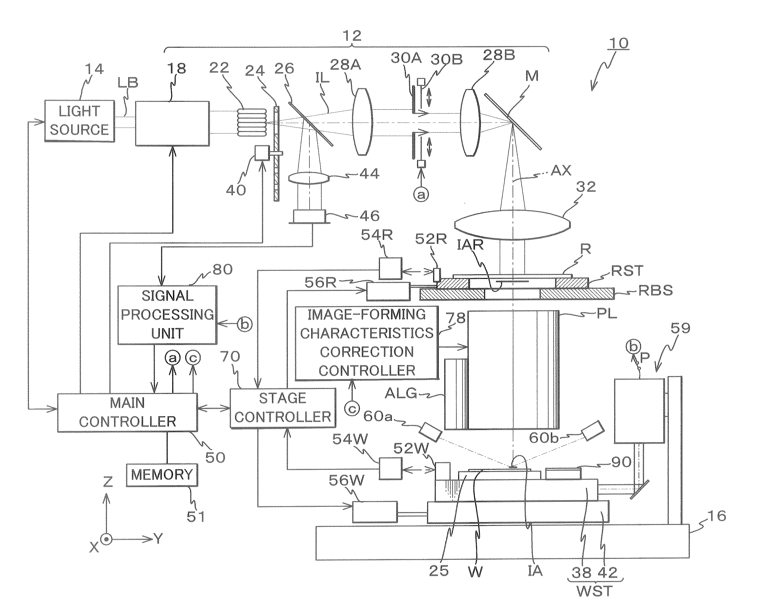
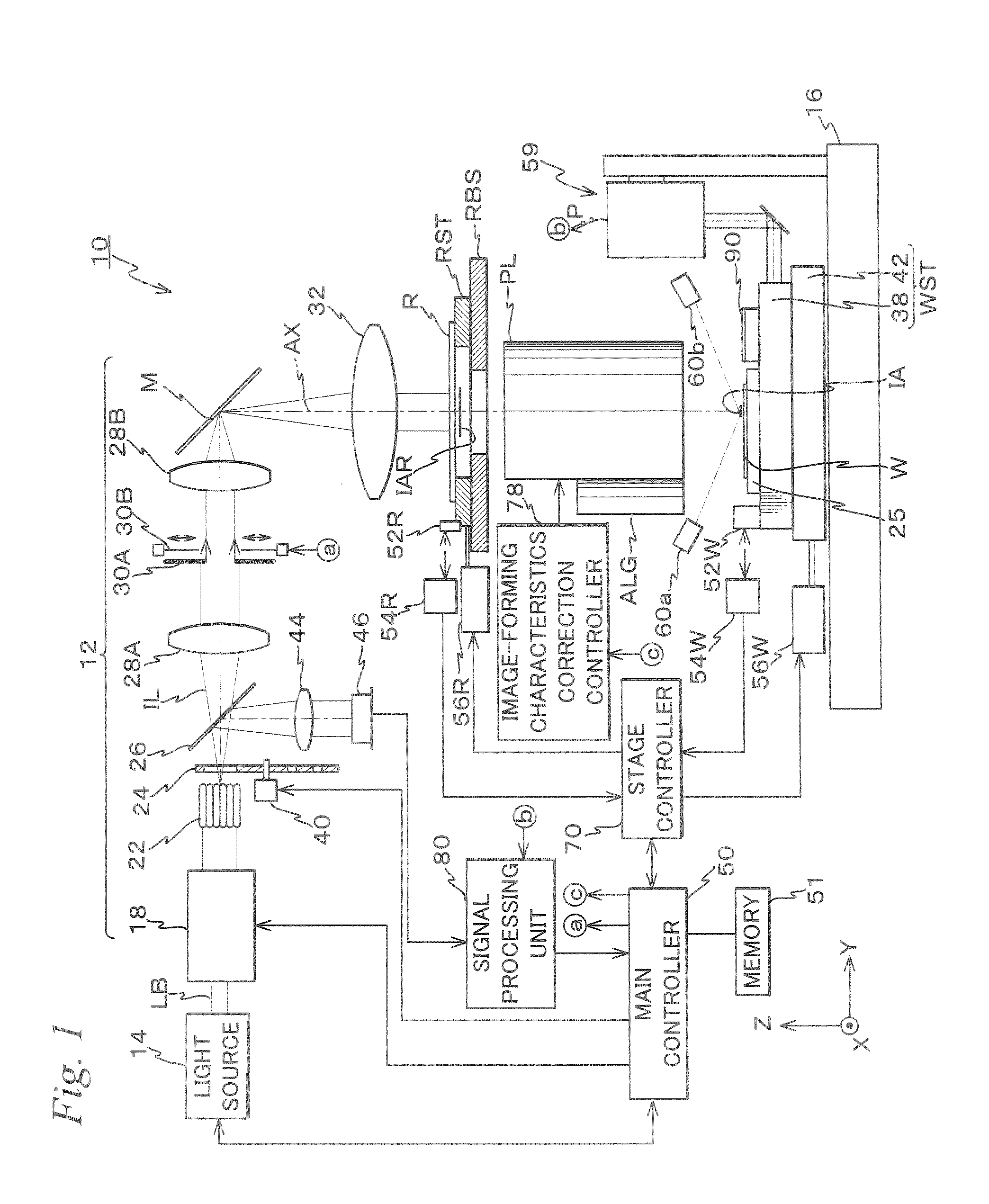
[0040]FIG. 1 shows the schematic configuration of an exposure apparatus 10 according to an embodiment to which the measurement method and the exposure method of the present invention are applied. Exposure apparatus 10 is a scanning projection exposure apparatus by a step-and-scan method, that is, a so-called scanning stepper.

[0041] Exposure apparatus 10 is equipped with: an illumination system including a light source 14 and an illumination optical system 12; a reticle stage RST as a mask stage that holds a reticle R as a mask; a projection optical system PT; a wafer stage WST as an object stage that holds a wafer W as an object and is freely movable within an XY plane; a control system that controls these sections; and the like. Further, although omitted in the drawings, of each of the above-described constituent portions, portions other than the light source and the...


PUM


Abstract

Light is irradiated on a light-shielding pattern on an object surface side of a projection optical system and light intensity distribution of the light having passed through the projection optical system and slits is detected while slits of an aerial image measuring unit on the image plane side of the projection optical system are moved within a plane perpendicular to the optical axis of the projection optical system. The information concerning the flare of the projection optical system is computed from the light intensity distribution, so that the influence of resist coated on a wafer used in a conventional exposing method can be eliminated, and highly accurate measurement of information concerning the flare can be realized. Further, measurement of information concerning the flare can be performed in a short time comparing to the exposing method because development process or the like of the wafer is not necessary.

Description

TECHNICAL FIELD [0001] The present invention relates to a measurement method and exposure method, more particularly to a measurement method in which information concerning flare of a projection optical system is measured, an exposure method using the measurement method, and a device manufacturing method using the exposure method. BACKGROUND ART [0002] In forming a fine pattern of an electronic device such as a semiconductor device (integrated circuit or the like) and a liquid crystal display device, a transfer method is used where a pattern of a mask or a reticle, on which a pattern to be formed is formed by proportionally magnifying by about four to five times thereinafter, generally referred to as “reticle”), is reduced on an object to be exposed such as a wafer by using a projection exposure apparatus. [0003] The projection exposure apparatus has shifted its exposure wavelength to a shorter wavelength side in order to cope with microfabrication of circuit patterns associated with...

Claims


Application Information

Patent Timeline
IPC IPC(8): G01B9/00G03F1/44G03F1/70G03F7/20H01L21/027
CPCG03F7/70591G03F7/70666G03F7/70941G03F7/7085G03F7/70683
Inventor HAGIWARA, TSUNEYUKI
Owner NIKON CORP
Why Eureka
Try Eureka