Magnetic film, manufacturing method thereof and thin film magnetic head

Inactive Publication Date: 2008-03-27
WESTERN DIGITAL TECH INC
View PDF16 Cites 2 Cited by
  • Summary
  • Abstract
  • Description
  • Claims
  • Application Information

AI Technical Summary

Benefits of technology

[0007] Embodiments in accordance with the present invention provide a magnetic disk drive capable of allowing higher data transfer rates and higher recording densities. According to the particular embodiment shown in FIG. 8, an upper magnetic core 37 and lower magnetic core 31 comprise a multi-layered magnetic film formed by alternately stacking a face-centered cubic (fcc) crystalline magnetic thin layer and a body-centered cubic (bcc) crystalline magnetic thin layer by plating. The plating bath is such that the temperature is about 30±1° C., pH is about 2.0−1.0 to 2.0+0.5, metal ion concentrations are about 5 to 25 (g / l) for Ni2+ and 5 to 15 (g / l) for Fe2+, saccharin sodium concentration is about 1.5±1.0 (g / l), sodium chloride concentration is about 25±5 (g / l), and boric acid concentration is about 25±5 (g / l). Since each layer's crystal structure is different from that of its adjacent lower layer, epitaxial growth is broken within each layer. Thus, since crystal grains are reduced in size, it is possible to lessen the decrease of the permeability μ at higher frequencies.

Problems solved by technology

While the recording frequency can be raised up to 700-800 MHz, however, this composition cannot fully meet the demand for longitudinal / perpendicular recording thin film magnetic heads capable of recording at 1000-2000 MHz.

Method used


Image

  • Magnetic film, manufacturing method thereof and thin film magnetic head
  • Magnetic film, manufacturing method thereof and thin film magnetic head
  • Magnetic film, manufacturing method thereof and thin film magnetic head

Examples


first embodiment

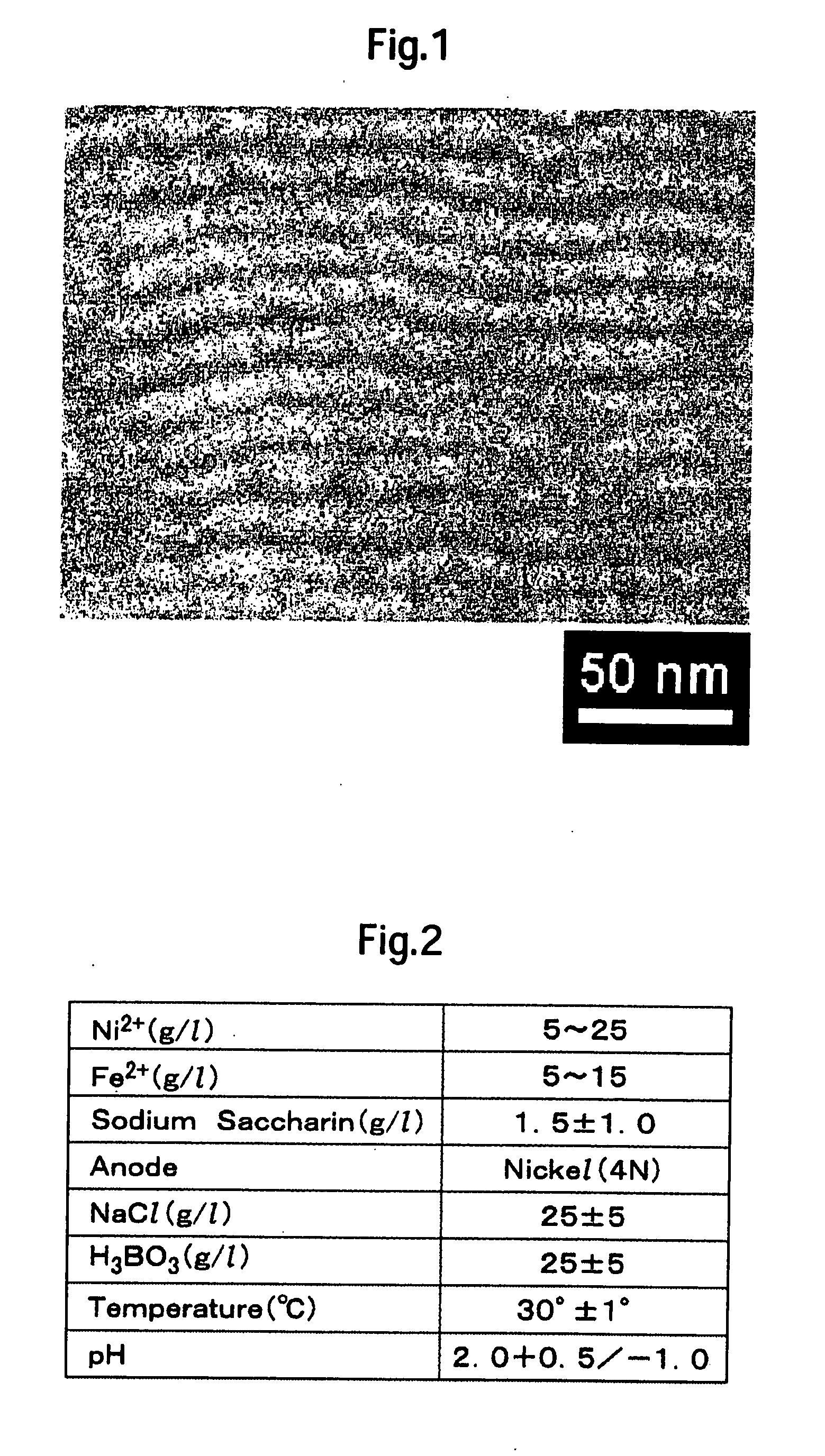
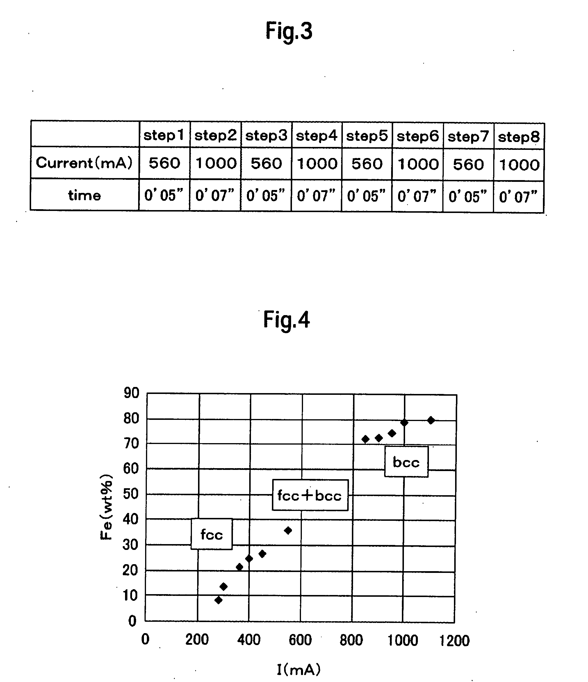
[0039] As a first embodiment, a magnetic film which comprises a magnetic core was formed by performing plating in the plating bath of FIG. 2 according to a current recipe shown in FIG. 3. Throughout the plating operation from the beginning to the end, the same plating tank was used. Note that time 0′ 05″ in FIG. 3 means 0 minute and 5 seconds. In the recipe, each of plating steps 1, 3, 5 and 7 deposits a 4.26 nm thick magnetic layer whose composition is Ni73Fe27 wt %. Likewise, each of steps 2, 4, 6 and 8 deposits a 4.5 nm thick magnetic layer whose composition is Ni22Fe78 wt %. Steps 1 through 8 were sequentially repeated 25 times, forming a 876 nm thick multi-layered film whose total composition is Ni46.8Fe53.2 wt %. To raise its total Bs, this plated multi-layered film is mainly composed of Fe rich magnetic thin layers of the bcc crystal structure. Plated fcc crystalline magnetic thin layers are inserted in order to break the epitaxial growth. Preferably, each magnetic thin layer...

second embodiment

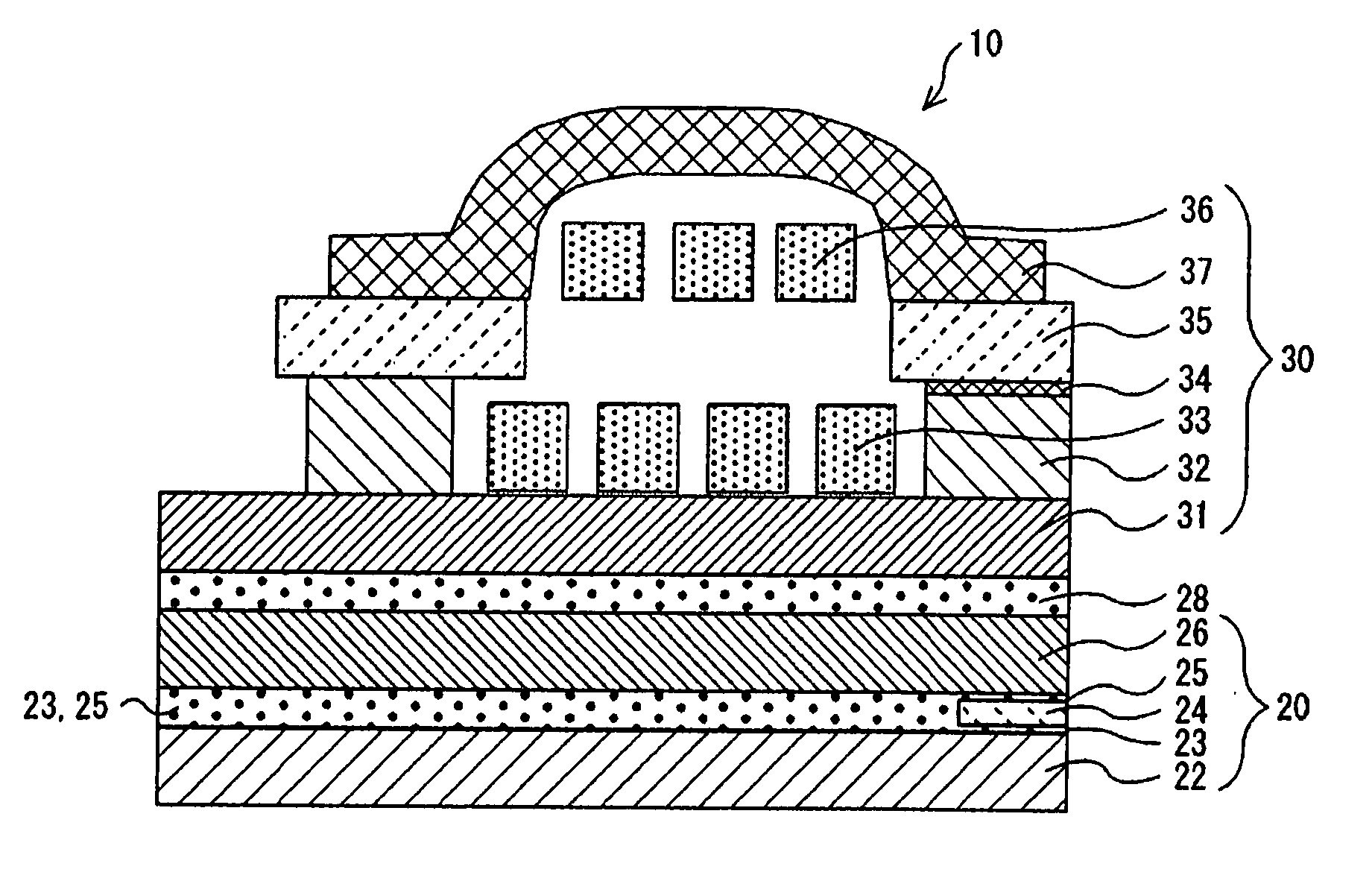
[0044] Then, turning again to FIG. 8, the following describes the configuration of a thin film magnetic head in which the above-mentioned NiFe multi-layered magnetic film is used to form the upper and lower magnetic cores in accordance with a This description is made along the manufacture process. On the non-magnetic substrate (not shown in the figure), the lower magnetic shield 22 and lower gap film 23 are formed. On the lower gap film 23, a MR, GMR or TMR sensor is formed as the read transducer 24. At each side of the read transducer 24, a magnetic domain control layer and electrode film are formed although they are not shown in the figure. Then, after the upper gap film 25 is formed on the read transducer 24 and electrode films, the upper magnetic film 25 is formed to complete the read head 20.

[0045] Then, after the insulation film 28 is formed on the top of the read head 20, the lower magnetic core 31 is formed thereon by depositing a Ni46Fe54 wt % film by plating. In more deta...


PUM

PropertyMeasurementUnit
Temperatureaaaaaaaaaa
Thicknessaaaaaaaaaa
Densityaaaaaaaaaa

Abstract

Embodiments of the present invention provide a magnetic disk drive capable of allowing higher data transfer rates and higher recording densities. According to one embodiment, an upper magnetic core and lower magnetic core comprise a multi-layered magnetic film formed by alternately stacking a face-centered cubic (fcc) crystalline magnetic thin layer and a body-centered cubic (bcc) crystalline magnetic thin layer by plating. The plating bath is such that the temperature is about 30±1° C., pH is about 2.0−1.0 to 2.0+0.5, metal ion concentrations are about 5 to 25 (g / l) for Ni2+ and 5 to 15 (g / l) for Fe2+, saccharin sodium concentration is about 1.5±1.0 (g / l), sodium chloride concentration is about 25±5 (g / l), and boric acid concentration is about 25±5 (g / l). Since each layer's crystal structure is different from that of its adjacent lower layer, epitaxial growth is broken within each layer. Thus, since crystal grains are reduced in size, it is possible to lessen the decrease of the permeability μ at higher frequencies.

Description

CROSS-REFERENCE TO RELATED APPLICATION [0001] The instant nonprovisional patent application claims priority to Japanese Patent Application No. 2006-168554 filed Jun. 19, 2006 and incorporated by reference in its entirety herein for all purposes. BACKGROUND OF THE INVENTION [0002] Magnetic recording and reproducing apparatuses, typically, magnetic disk drives, have been required to provide higher data transfer rates and higher recording densities. This has resulted in the use of higher coercivity recording media. With regard to thin film magnetic heads, it is desired to maximize the coil current to recording magnetic field conversion efficiency since the recording frequency must be raised to cope with the demand for higher data transfer rate. To raise the conversion efficiency, the hysteresis loss of the magnetic cores should be reduced by using a low Hc / Hk material to lower their coercivity (Hc) along the hard axis or anisotropy magnetic field (Hk). Further, to reduce the eddy loss,...

Claims


Application Information

Patent Timeline
IPC IPC(8): G11B5/33H04R31/00
CPCG11B5/1278G11B5/147Y10T428/115G11B5/313Y10T29/49032G11B5/3116
Inventor KUDO, KAZUEOIKAWA, GENMARUYAMA, YOHJISAIKI, NORIYUKISHIINA, HIROMI
Owner WESTERN DIGITAL TECH INC
Why Eureka
Try Eureka