Controlled phase transition of metals
a phase transition and metal technology, applied in the field of physical chemistry, can solve the problems of wasting 90% of energy input as heat, unable to harness electromagnetic energy for controlling liquid/solid phase transition, and unable to achieve the effect of transforming metals quickly and reducing energy consumption
- Summary
- Abstract
- Description
- Claims
- Application Information
AI Technical Summary
Benefits of technology
Problems solved by technology
Method used
Image
Examples
example 1
Apparatus for Generating Electromagnetic Field
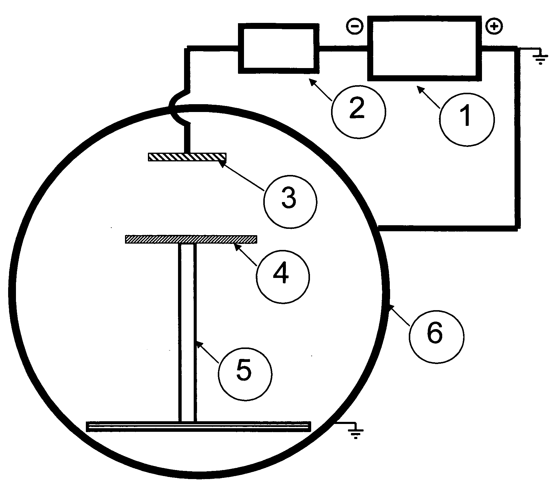
[0030]A vacuum chamber was constructed of ⅜″ thick A6 steel with a diameter of 30 in and a length of 36 in. The chamber was pumped with a VHS 6 oil diffusion pump with 400 ml of DuPont 704 diffusion pump oil. The pump was backed by a 30 CFM Pfeiffer mechanical pump with 1 liter of Stokes C-77 pump oil. The chamber was rough pumped by a Leybold E-75 pump with a WU 500 blower package with Fomblin oil. The pump down of the chamber was controlled by internally designed circuits utilizing an MKS 636 baratron and a BP ion gauge. The apparatus includes a 6×1×20 in, 99.99% pure nickel target with water cooling and two power inputs. This cathode was driven by a Miller 304 CC / CV power supply and a Miller analog pulsing unit.
[0031]An alternative to the 6×20 in target cathode are small round target cathodes with a surface diameter of 1 to 6 in. This target configuration can assist in the localization of the transfer of current from the cathode to th...
example 2
Electromagnetic Field Induced Phase Transition of Aluminum
[0032]Aluminum was selected as the substrate. The pulse current generated by the electromagnetic field using the apparatus described in Example 1 was 300 Hz. Localization of the current outflow from the cathode to the anode in the pulsed mode must be locally confined. At the reported powers, the area of electron flow was confined consistently to an area approximately 3 inches in diameter. This confinement allows creation of a coherent beam in which the EM field travels.
[0033]An 8×¼×12 in 6061T6 aluminum plate was placed in an aluminum 2×2×¼ in wall thickness square channel of conductive aluminum that was 22 in tall. This placed the substrate 8 in from the surface of the target. The apparatus was constructed as described in Example 1 and the chamber was pumped to a level of 5E-4 Torr. The power supply was set to 300 amps, 20 V output. The pulsing unit was set with at background current of 75 amps, a pulse width of 2 ms, and a ...
example 3
Electromagnetic Field Induced Phase Transition of Silicon
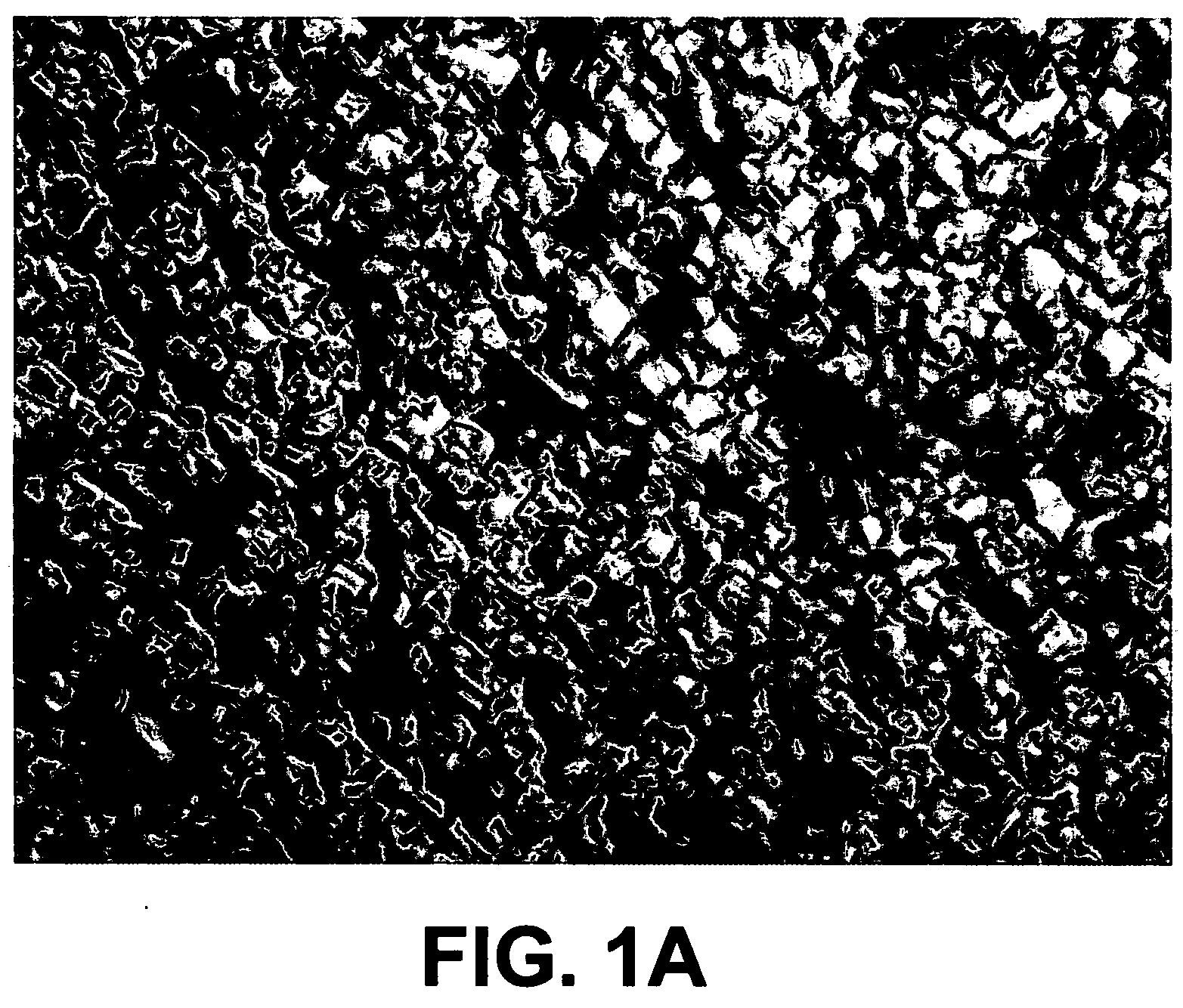
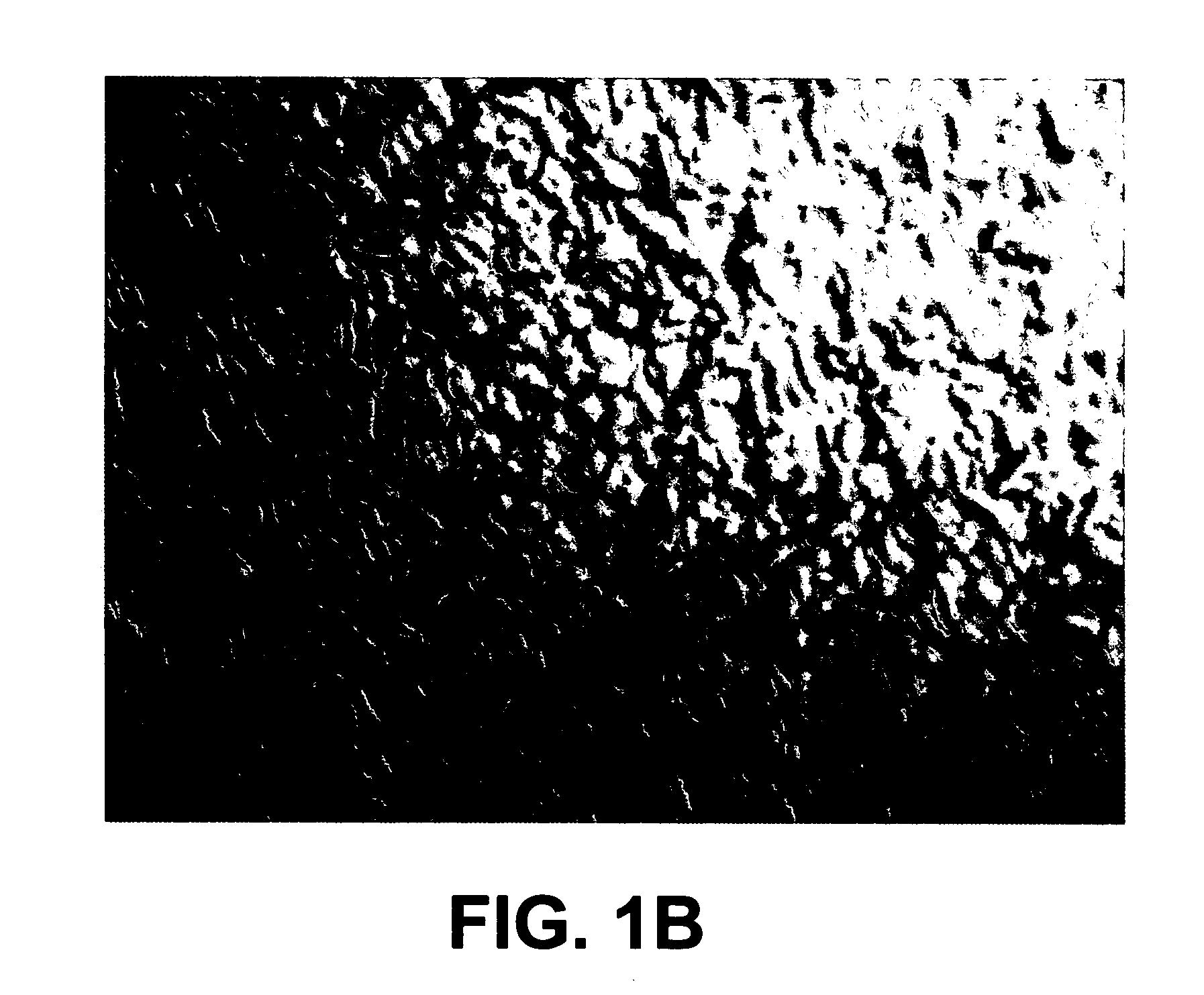
[0036]A 3-inch diameter silicon wafer on a 8×¼12 in copper plate was placed on an aluminum 2×2×¼ in wall thickness square channel that was 28 in tall. The plate was placed 8 in from the surface of the target. The silicon disk was placed on top of the copper plate, smooth side up in the chamber of the apparatus described in Example 1 using the conditions identical to those described in Example 2. The silicon began to flow at 39° C., which is significantly lower than heat-induced melting, which requires a temperature of 1414° C. FIGS. 1A and 1B compare a 40× magnified surface of the silicon wafer pre- and post treatment.
[0037]The rough side of the silicon disc changed from a single crystal to a polycrystalline surface with visual evidence of liquefied flow. The obvious pattern of the original crystal structure was no longer apparent. The originally flat copper substrate plate was warped by several millimeters. The melting point ...
PUM
| Property | Measurement | Unit |
|---|---|---|
| frequency | aaaaa | aaaaa |
| temperatures | aaaaa | aaaaa |
| diameter | aaaaa | aaaaa |
Abstract
Description
Claims
Application Information
 - R&D
- Intellectual Property
- Life Sciences
- Materials
- Tech Scout
- Unparalleled Data Quality
- Higher Quality Content
- 60% Fewer Hallucinations
Browse by: Latest US Patents, China's latest patents, Technical Efficacy Thesaurus, Application Domain, Technology Topic, Popular Technical Reports.
© 2025 PatSnap. All rights reserved.Legal|Privacy policy|Modern Slavery Act Transparency Statement|Sitemap|About US| Contact US: help@patsnap.com


