Apparatus and method for optical switching with liquid crystals and birefringent wedges

a technology of liquid crystals and wedges, applied in the field of optical switching, can solve the problems of increasing the coupling loss to an output port, unable to achieve the promise, and creating significant challenges for control and long-term stability

Active Publication Date: 2008-04-17
II VI DELAWARE INC
View PDF24 Cites 22 Cited by
  • Summary
  • Abstract
  • Description
  • Claims
  • Application Information

AI Technical Summary

Problems solved by technology

Waveguided approaches (e.g. planar light circuits or PLCs) have been proposed for such functions but to date their promise has not been realized because of technical problems remaining to be overcome.
It is the flexibility of the beam steering mechanism that makes MEM devices so promising and at the same time creates significant challenges for control and long term stability.
Small deviations (<0.1 degree) in signal deflection can dramatically increase the coupling losses to an output port.
Fabrication of the MEMs arrays requires an expensive processing facility, which makes them a costly solution for low volume applications.
Also, since unwanted surface reflections are always present to some degree, crosstalk can be a significant problem.
While it is easy to conceptualize a 1×2 LC-based switch, unlike the MEM device technology, generalization to 1×M with M>2 is problematic because of the discrete 2-state nature of the polarization switching.
Cascading schemes have been proposed for broadband signal routing; however, these approaches are not amenable to wavelength-selective switching in a DWDM network.

Method used


Image

  • Apparatus and method for optical switching with liquid crystals and birefringent wedges
  • Apparatus and method for optical switching with liquid crystals and birefringent wedges
  • Apparatus and method for optical switching with liquid crystals and birefringent wedges

Examples


first embodiment

[0060]FIG. 9 illustrates the invention. It is a 1×4 optical routing switch for a fiber optic system. It is not wavelength specific. Light exits the input fiber 902 and passes through a collimator / BD / retarder coupling assembly 904. The two parallel beams then pass through the LC / wedge switching assembly 906 and through the action of the switch the beams are deflected to 1 of 4 output ports 908. Each output port contains a retarder / BD / collimator assembly 910 for coupling to that port's output fiber. The switch assembly is for concreteness here assumed to have its LC and wedge configuration according to the bifurcation diagram of FIG. 7b. With reference to FIG. 7b, it is clear that two of the beams output from the switch assembly have their polarizations orthogonal to the input polarization. For these two beams, which correspond to output ports 1912 and 3914 in FIG. 9, the half wave retarders 916 and 918 in the coupling assembly must be moved, as shown in the figure, to the opposite be...

second embodiment

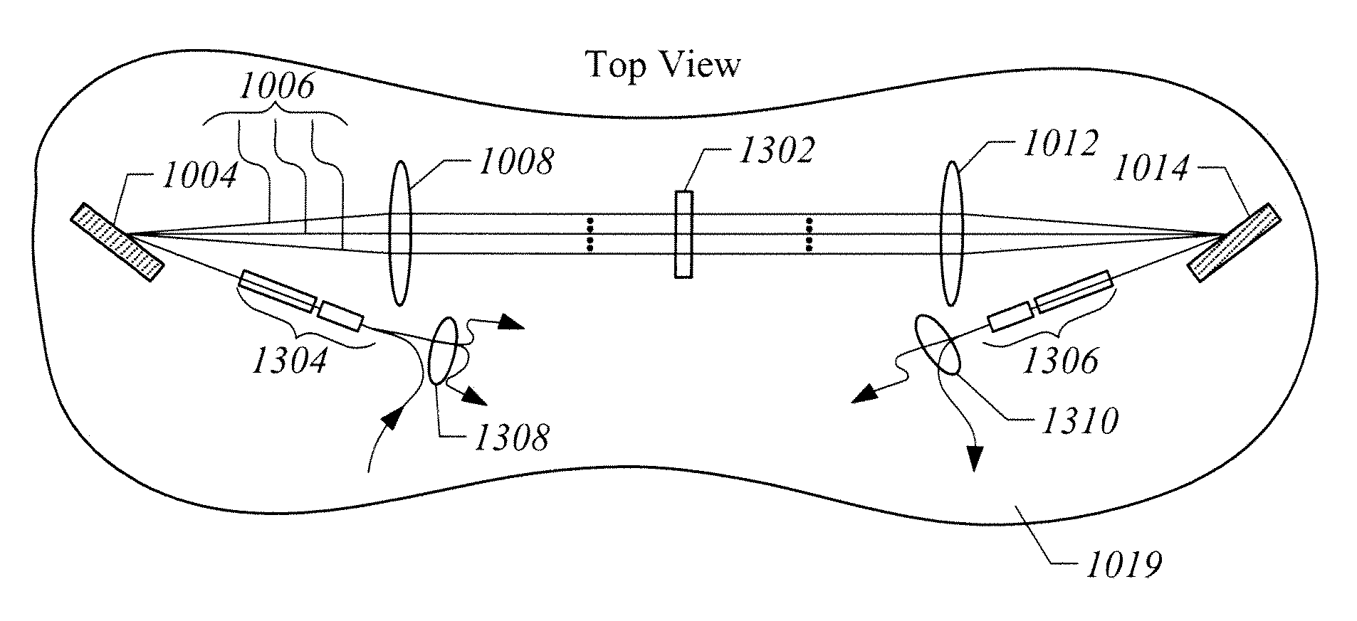
[0061]FIG. 10 illustrates a second embodiment which functions as a 1×4 wavelength switch for a WDM fiber optic network. With reference to FIG. 10a, this device comprises (1) an input fiber coupling assembly 1002 (i.e. collimator / BD / waveplate) which provides two parallel beams of identical polarization, (2) a dispersive means 1004 (e.g., a grating) which takes these polarized beams and separates them into their component wavelengths 1006, (3) a means with optical power 1008 (e.g. a lens) in the path of the dispersed beams which serves two functions: it converts the diverging dispersed beams into an array of parallel beams and focuses the beams on the switching assembly, (4) an LC / wedge switching assembly 1010, (5) a second means with optical power 1012 (lens) that performs the inverse functions of the first means with optical power, collimating the dispersed beams and focusing these beams to the same point on (6) a second dispersive means 1014 (e.g., a second grating) which combines ...

third embodiment

[0065]FIG. 11 is a 1×4 wavelength-selective switch that contains a reflective means, thereby eliminating the second means with optical power as well as the second dispersive means of the previous embodiment. With reference to FIG. 11a, light containing N discrete wavelengths exits the input fiber 1102, passing first through an input coupling assembly 1104 which produces two parallel beams with the same polarization. A dispersive means 1108 (here a diffraction grating) separates the beams into N pairs of beams 1110, one pair for each component wavelength. A means with optical power 1112 (here a convex spherical lens) focuses the separate beams onto the LC switch assembly 1114. A reflective means after the switch assembly then returns the light in reverse order back through the LC assembly, the means with optical power, and the dispersive means after which it is coupled back to 1 of 4 four output ports via the coupling array. A detail of the switching assembly is illustrated in FIG. 1...


PUM

PropertyMeasurementUnit
wavelength rangeaaaaaaaaaa
adhesiveaaaaaaaaaa
wavelengthaaaaaaaaaa

Abstract

An optical switch includes an optical waveguide to route an input optical beam. At least one polarization switch receives the input optical beam from the optical waveguide. At least one birefringent wedge is associated with the at least one polarization switch. The at least one polarization switch and at least one birefringent wedge operate to direct the input optical beam to two or more output locations through control of the polarization switch.

Description

CROSS REFERENCE TO RELATED APPLICATIONS [0001] This application is a divisional application of U.S. patent application Ser. No. 11 / 318,068, entitled, “Apparatus And Method For Optical Switching With Liquid Crystals And Birefringent Wedges,” filed on Dec. 23, 2005, which claims the benefit of U.S. Provisional Application No. 60 / 639,107, entitled “A 1×M Optical Switch Utilizing Liquid Crystals And Birefringent Wedges,” filed on Dec. 23, 2004, the contents of which are hereby incorporated by reference in their entirety.FIELD OF THE INVENTION [0002] The present invention relates to optics. More particularly, the invention relates to beam routing in wave-guided optical systems. BACKGROUND OF THE INVENTION [0003] A dense wavelength division multiplexed (DWDM) optical network, as with any information network, requires switches to perform routing of signals. DWDM networks pass several information channels along the same optical waveguide (e.g., optical fiber). Each channel corresponds to a ...

Claims


Application Information

Patent Timeline
Patent Type & Authority Applications(United States)
IPC IPC(8): B29C65/14B29C65/52
CPCG02B6/272G02B6/2931Y10T156/10G02F1/31G02F1/13363
Inventor WASHBURN, HUDSONXUE, MENG
Owner II VI DELAWARE INC
Why Eureka
Try Eureka