Method for removing foreign matter from substrate surface

a technology for removing foreign matter and substrate surface, which is applied in the direction of photomechanical treatment, cleaning using liquids, instruments, etc., can solve the problems of difficult removal of foreign matter from the substrate, no electrical repulsive force, etc., and achieve the effect of suppressing surface roughness and preventing reattachment of once removed foreign matter to the substrate surfa

Active Publication Date: 2008-04-24
ASAHI GLASS CO LTD
View PDF7 Cites 17 Cited by
  • Summary
  • Abstract
  • Description
  • Claims
  • Application Information

AI Technical Summary

Benefits of technology

[0013]Under these circumstances, in order to overcome the above-described problems of prior art, it is an object of the present invention to provide a method for removing foreign matters, capable of easily removing inorganic foreign matters strongly attached to the surface of a substrate made of silicon or glass or to the surface of an inorganic coating formed on the substrate surface while the increase of the surface roughness is suppressed, and further capable of preventing reattachment of once removed foreign matters to the substrate surface.
[0026]According to the foreign matter removal method of the present invention, inorganic foreign matters strongly attached to the surface of a substrate made of silicon or glass or to the surface of an inorganic coating formed on the substrate surface can easily be removed while the increase of the surface roughness is suppressed, and further, reattachment of once removed foreign matters to the substrate surface can be prevented.

Problems solved by technology

However, in a case where an acidic solution having a pH<7 is used as a chemical solution for the lift-off process, pH of the chemical solution is close to the equipotential, the surface potential of the substrate and the foreign matters is substantially 0 and accordingly substantially no electrical repulsive force is obtained.
Thus, not only removal of the foreign matters from the substrate is difficult, but also the foreign matters suspended in the chemical solution, after once removed from the substrate, are likely to be attached to the substrate again.

Method used


Image

  • Method for removing foreign matter from substrate surface
  • Method for removing foreign matter from substrate surface
  • Method for removing foreign matter from substrate surface

Examples


example 3

[0161]The same treatment as in Example 1 is carried out except that the lamp application conditions in process 1 and the conditions of the spin method in process 2 are changed to the following conditions, and evaluations are carried out in the same manner as in Example 1. The results of the evaluations 1 and 2 are shown in the following Table.

(Process 1)

[0162]Dielectric barrier discharge lamp filled with Xe2 gas (dominant wavelength: 172 nm)

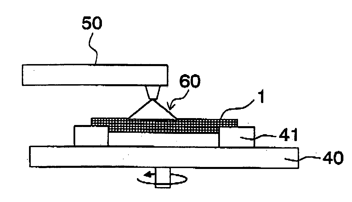
[0163]Luminance at the window wall 30: 10 mW / cm2

[0164]Gas (N2 / O2): 99.9 / 0.1 vol %

[0165]Exposure time; 30 min (application amount: 18 J / cm2)

[0166]Surface potential: −15 mV (at a pH of 3.1)

(Process 2)

[0167]Spin method (acidic solution): 0.1 wt % HP aqueous solution (room temperature, pH=2), 50 rpm×5 min

[0168]Rinsing: Deionized water (room temperature), 150 rpm×3 min

[0169]Spin drying: 1,200 rpm×1 min

example 4

[0170]The same treatment as in Example 1 is carried out except that the lamp application conditions in process 1 and the conditions of the spin method in process 2 are changed to the following conditions, and evaluations are carried out in the same manner as in Example 1. The results of the evaluations 1 and 2 are shown in the following Table.

(Process 1)

[0171]Dielectric barrier discharge lamp filled with Kr gas (dominant wavelength: 146 nm) Luminance at the window wall 30: 5 mW / cm2

[0172]Gas (N2 / O2): 99.9 / 0.1 vol %

[0173]Exposure time: 5 min (application amount: 1.5 J / cm2)

[0174]Surface potential: −30 mV (at a pH of 3.1)

(Process 2)

[0175]Spin method (acidic solution): 0.1 wt % HF aqueous solution (room temperature, pH=2), 50 rpm×5 min

[0176]Rinsing: Deionized water (room temperature), 150 rpm×3 min

[0177]Spin drying: 1,200 rpm×1 min

example 5

[0178]The same treatment as in Example 1 is carried out except that the lamp application conditions in process 1 and the conditions of the spin method in process 2 are changed to the following conditions, and evaluations are carried out in the same manner as in Example 1. The is results of the evaluations 1 and 2 are shown in the following Table.

(Process 1)

[0179]Dielectric barrier discharge lamp filled with Kr gas (dominant wavelength: 146 nm)

[0180]Luminance at the window wall 30: 5 mW / cm2

[0181]Gas (N2 / O2): 95 / 5 volt

[0182]Exposure time: 15 min (application amount: 4.5 J / cm2)

[0183]Surface potential: −50 mV (at a pH of 3.1)

(Process 2)

[0184]Spin method (acidic solution): 0.1 wt % HF aqueous solution (room temperature, pH=2), 50 rpm×5 min

[0185]Rinsing: Deionized water (room temperature), 150 rpm×3 min

[0186]Spin method (alkali solution): 1 wt % ammonia aqueous solution (room temperature)[0187]Ultrasonic waves at 1 MHz applied at the time of supply[0188]50 rpm×4 min

[0189]Rinsing: Deioniz...


PUM

PropertyMeasurementUnit
surface voltageaaaaaaaaaa
wavelengthaaaaaaaaaa

Abstract

To provide a method for removing foreign matters, capable of easily removing inorganic foreign matters strongly attached to the surface of a substrate made of silicon or glass or the surface of an inorganic coating formed on the substrate surface while the increase of the surface roughness is suppressed, and further capable of preventing reattachment of once removed foreign matters to the substrate surface.A method for removing inorganic foreign matters from the surface of a substrate made of silicon or glass or the surface of an inorganic coating formed on the surface of the substrate, which comprises applying a light beam in a wavelength range which makes the light absorption coefficient of at least one of a material of the substrate, a material of the inorganic coating and the inorganic foreign matters be at least 0.01 / cm, to the surface of the substrate or to the surface of the inorganic coating in an application amount of at least 10 J / cm2 in an oxygen- or ozone-containing atmosphere, and exposing the surface of the substrate or the surface of the inorganic coating having a negative surface potential to an acidic solution having a pH≦6.

Description

BACKGROUND OF THE INVENTION[0001]1. Field of the Invention[0002]The present invention relates to a method for removing inorganic foreign matters strongly attached to the surface of a substrate made of silicon or glass to be used as a silicon wafer, a photomask substrate or a photomask blank, the surface of a glass substrate for a template to be used for nanoimprinting, the surface of a substrate made of glass to be used as a substrate for various display devices, or the surface of an inorganic coating formed on the surface of such a substrate.[0003]2. Discussion of Background[0004]Heretofore, in a process for producing an integrated circuit, photolithography process which comprises reduction projection of a circuit pattern on a mask onto a wafer by using an exposure device to form an integrated circuit on the wafer has been widely utilized. Along with high integration and high functionality of integrated circuits, microsizing of an integrated circuit is in progress, and an exposure ...

Claims


Application Information

Patent Timeline
Patent Type & Authority Applications(United States)
IPC IPC(8): B08B3/12C23G1/00B08B6/00
CPCC03C15/00C03C23/0005H01L21/02054G03F1/82C03C23/0075H01L21/306H01L21/02
Inventor IKUTA, YOSHIAKI
Owner ASAHI GLASS CO LTD
Why Eureka
Try Eureka