Solid state fluid level sensor

a fluid level sensor and solid state technology, applied in positive displacement liquid engines, instruments, machines/engines, etc., can solve the problems of bilge pump activation switches typically worn out, difficult access for repair and replacement, and switch failur

Active Publication Date: 2008-04-24
TOUCHSENSOR TECH
View PDF23 Cites 14 Cited by
  • Summary
  • Abstract
  • Description
  • Claims
  • Application Information

AI Technical Summary

Benefits of technology

[0014] The housing or container holds first and second electrode patterns in a vertical orientation and has ribs on the housing's sides to allow debris found in a bilge to slough off. By careful selection of materials, the container can resist biological attack (e.g., fungus or algae) and prevent fouling from other materials that might stick to the container otherwise. In the vertical position, gravity also helps to allow the anticipated contamination to slough off.
[0023] The cost and complexity of the sensor is reduced since a relay or switch is not required.
[0025] In the preferred form, an active electrical component preferably configured as a surface mount application specific integrated circuit (ASIC), is located at each sensor. Preferably, the ASIC is connected to the center pad electrode and to the outer electrode of each sensor. The ASIC acts to amplify and buffer the detection signal at the sensor, thereby reducing the difference in signal level between individual sensors due to different lead lengths and lead routing paths. A plurality of sensors may be arranged on the substrate.

Problems solved by technology

Over time, however, bilge debris and other sources of contamination often prevented the mechanical components from moving as intended, causing switch failure.
In addition, prior art bilge pump activation switches typically wore out several times during the life of a boat and, being located in a boat's nether regions, were difficult to access for repair and replacement.
Prior art mechanisms for detection of an excessive bilge water level employed mechanical floatation systems, causing a switch to be actuated whenever the water reached such an undesired level.
Bilge fluid or water eventually renders mechanical level sensing systems inoperative in part because bilge fluid can contain many forms of corrosive waste.
Replacing failed parts a bilge level sensing system can be very expensive and troublesome, since a skilled technician must enter the bilge to perform the work.
The bilge water is sensed as a dielectric, in a manner of speaking, and so the sensor is susceptible to false alarms or missed detections once the contamination accompanying bilge inflow has accumulated in the bilge and contaminated the area around the sensor, and sloshing bilge water is likely to cause the bilge control to actuate when the bilge level does not require pumping.
Here again, bilge water is sensed as a dielectric, in a manner of speaking, and so the sensor is susceptible to false alarms or missed detections once the contamination accompanying bilge inflow has accumulated in the bilge and contaminated the area around the sensor, and sloshing bilge water is likely to cause the bilge control to actuate when the bilge level does not require pumping.
The probes are in contact with the bilge water, and so the probe sensors are susceptible to false alarms or missed detections once the contamination accompanying bilge inflow has accumulated in the bilge and contaminated the probes.
This reference is silent on the need to keep bilge water away from the sensors, but the bilge water is sensed as a dielectric, in a manner of speaking, and so the sensor is susceptible to false alarms or missed detections once the contamination accompanying bilge inflow has accumulated in the bilge and contaminated the area around the sensors.

Method used


Image

  • Solid state fluid level sensor
  • Solid state fluid level sensor
  • Solid state fluid level sensor

Examples


Embodiment Construction

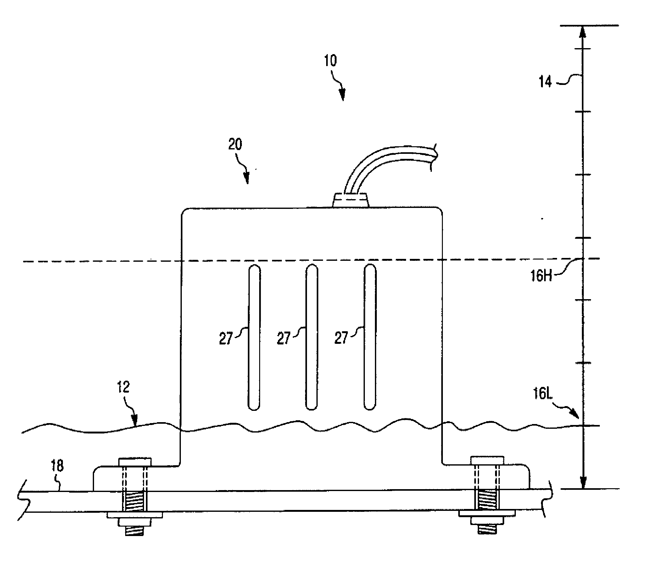
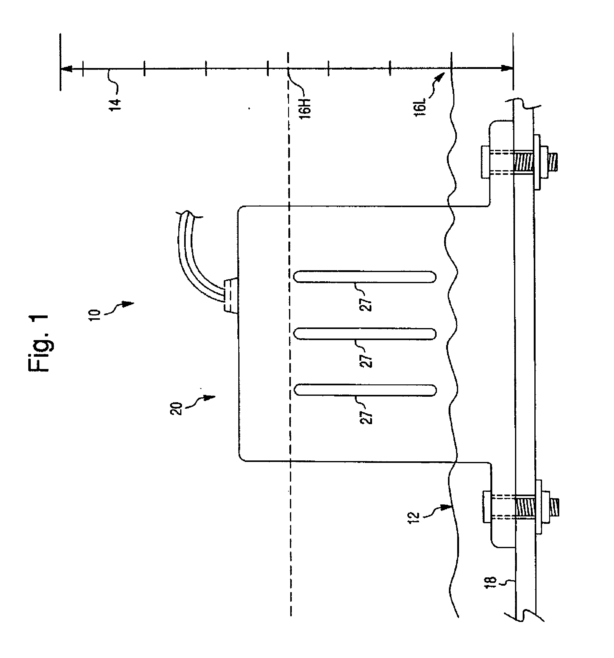
[0035] Referring to the exemplary embodiment illustrated in FIGS. 1-5, a bilge or fluid containment vessel 10 is bounded by a fluid tight wall or surface 18 and at times contains bilge water or some other fluid 12. The fluid level in the bilge rises and falls and the fluid level 14 is measurable over a selected dimension such as that shown by the vertical scale in FIG. 1. As the fluid level rises or falls, a fluid / air interface 16 can be sighted or measured along the fluid level scale 14. In the typical marine application, bilge 10 contains fluid 12 such as waste water or seawater that leaks through the hull or deck, and when the bilge fluid level 16 is excessively high (e.g., at a selected upper or trigger level 16H), fluid 12 must be pumped out, usually with an electrically powered pump (not shown) that is selectively energized when the excessively high fluid level 16H is detected. The fluid level is sensed while pumping progresses and the pump is turned off when the level of flui...


PUM

PropertyMeasurementUnit
widthaaaaaaaaaa
widthaaaaaaaaaa
total timeaaaaaaaaaa

Abstract

A sensor system for sensing liquid level in a bilge, for use in automatic bilge pump actuation. First and second field effect sensors are potted or sealed within a container or the bilge wall and are aligned in a vertical array and each comprise a substantially planar pattern of “electrodes” or conductive traces disposed on a printed circuit board (PCB) along with integrated circuits used to create a loop or arc-shaped electric field. As bilge liquid rises to the proximity or level of the field effect sensors, a change in the arc-shaped electric field is sensed and, in response, a bilge pump is automatically actuated to pump liquid out of the bilge. Optionally, the pump control can be programmed by use of a microprocessor to permit control of on-off timing and is prevent undesirable effects of “sloshing.”

Description

BACKGROUND OF THE INVENTION [0001] 1. Field of the Invention [0002] The present invention relates to sensors for detecting the presence of a fluid, automatic systems for actuating pumps in response to detecting a fluid level and sensors mounted in the bottom of a boat bilge tank activating a bilge pump when the bilge fluid level reaches a preset distance above the bottom of the bilge tank. [0003] 2. Discussion of the Prior Art [0004] In the past, bilge pumps have been activated manually or by mechanical float type switches with mercury or point contacts to complete an electrical circuit activating a pump. Pressure switches have also been used. These prior art switches worked adequately when initially installed. Over time, however, bilge debris and other sources of contamination often prevented the mechanical components from moving as intended, causing switch failure. In addition, prior art bilge pump activation switches typically wore out several times during the life of a boat and,...

Claims


Application Information

Patent Timeline
Patent Type & Authority Applications(United States)
IPC IPC(8): F04B49/06H05K3/30
CPCF04D15/0218G01F23/261G01F23/265G01F23/266Y10T29/4913H05K1/0268H05K1/16F04B17/03F04B49/02G01F23/268F04D15/02G01F23/26G01F23/284
Inventor BURDI, ROGER D.RENIGER, BRUCE L.
Owner TOUCHSENSOR TECH
Why Eureka
Try Eureka